Close
0%
0%

1284P-Target

A development board for the Atmega1284P.

Similar projects worth following
It's a development board for the DIP version of the Atmega1284P. It has a 10-pin ICSP header for flashing code via a cheap USBASP and also has a UART header to be bootloader friendly.

I've been wanting to do this for quite some time.  I've been wanting to get a Atmega1284P off of my breadboard for quite some time.  I've started doing a design a few times in the past, only to be put off by the cost of having a board made but have recently found a board fab that can make the board for a reasonably low price.

At the current time of this writing, the first revision design is not complete.
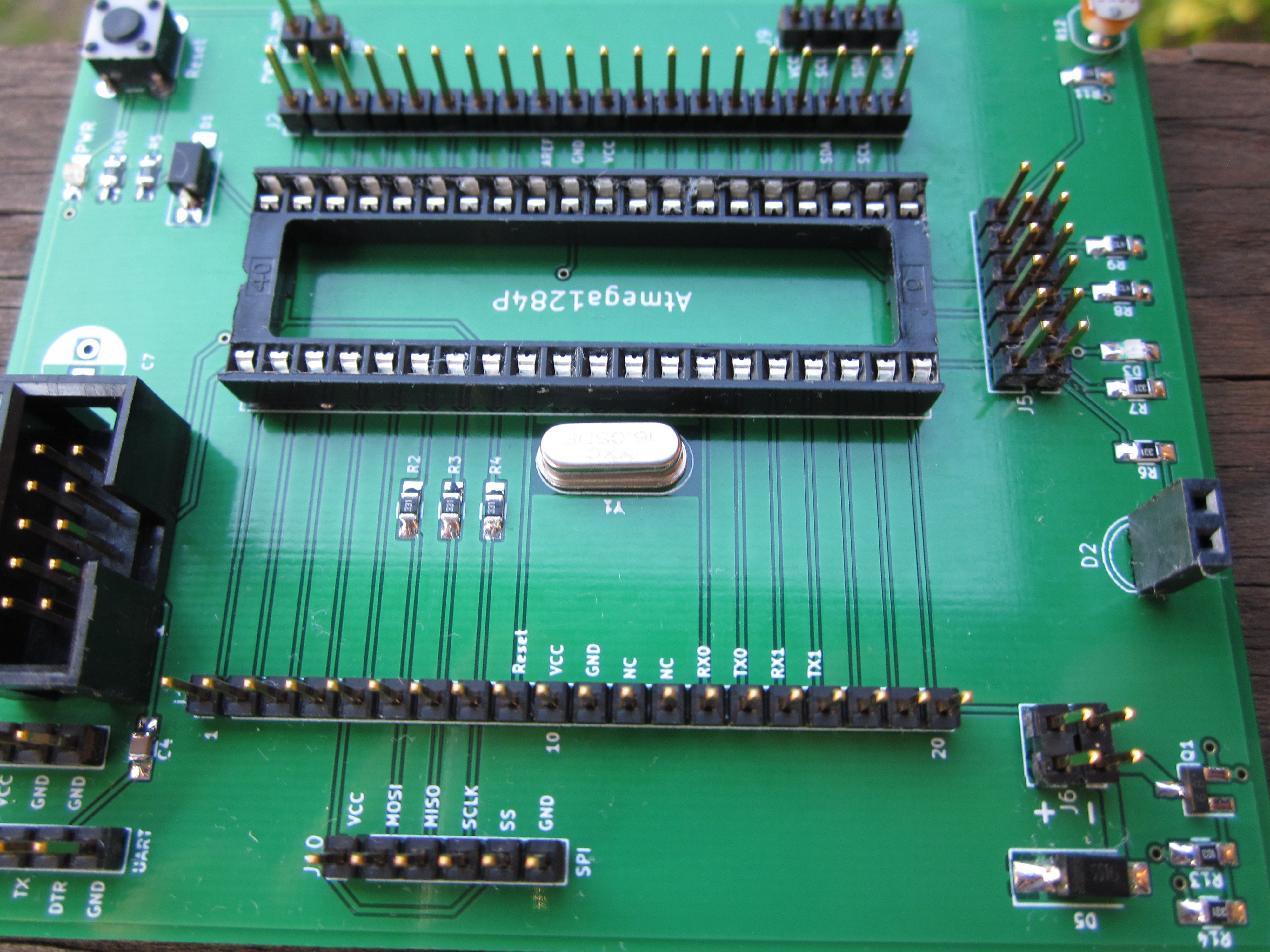
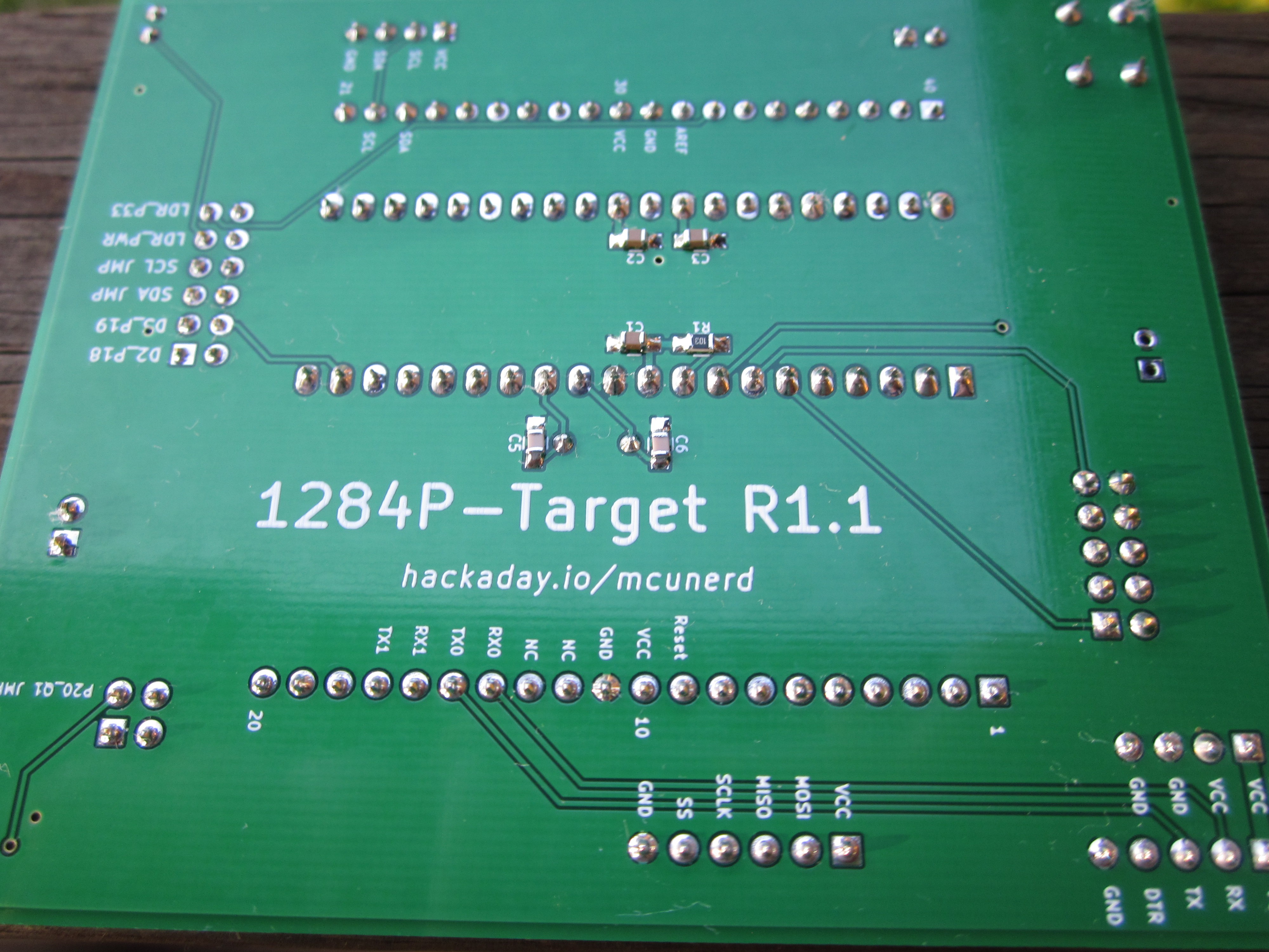
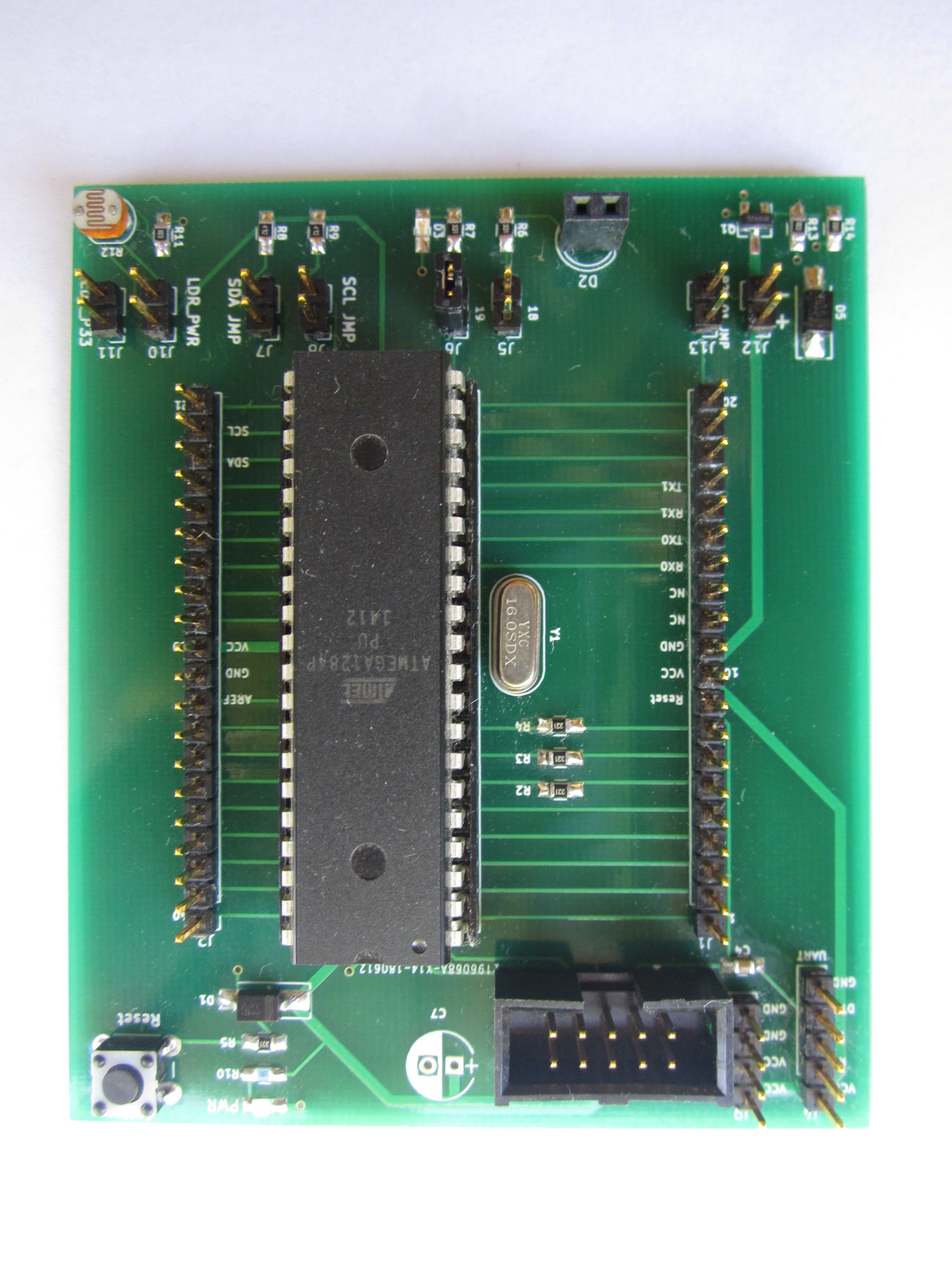
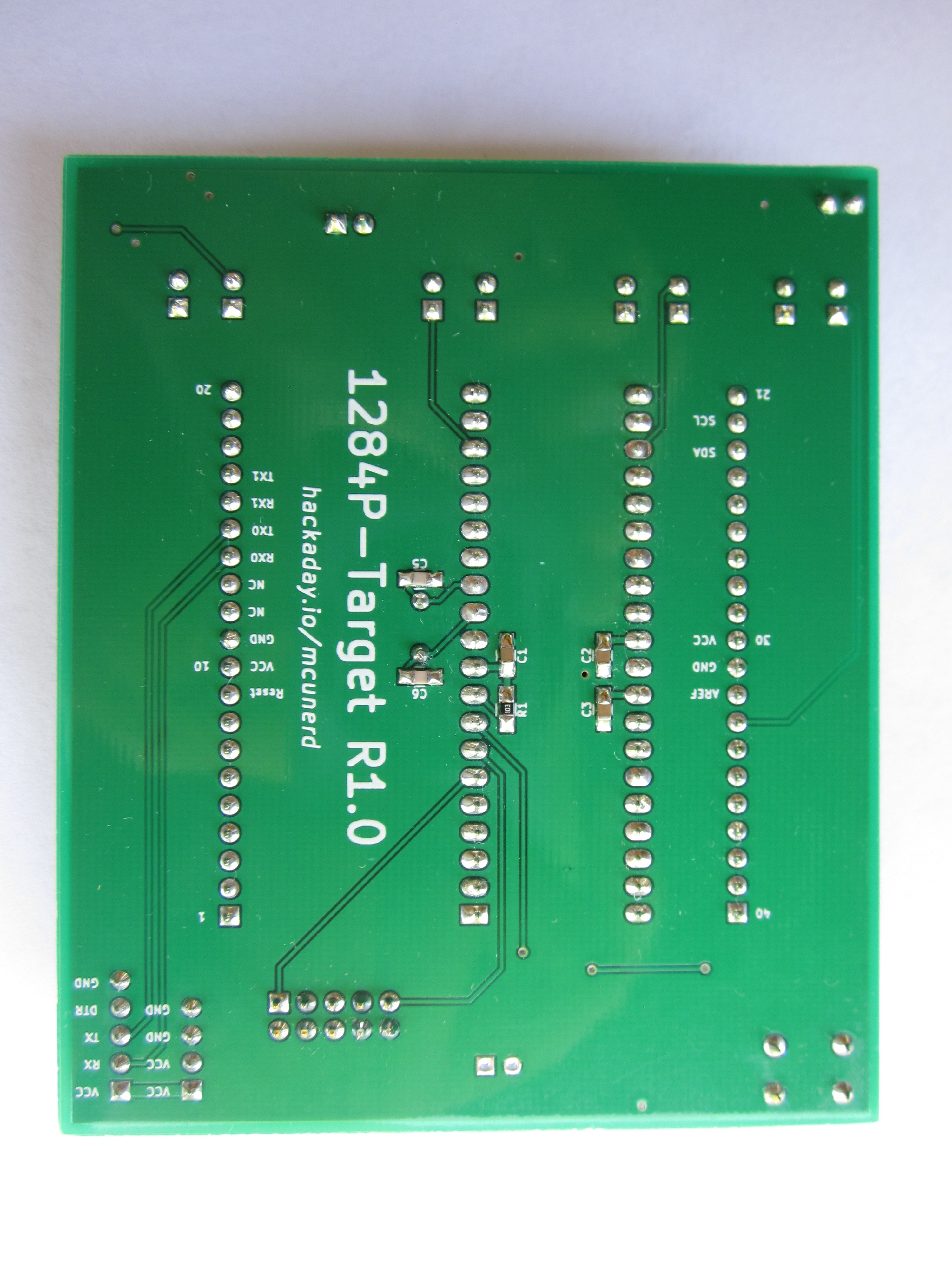
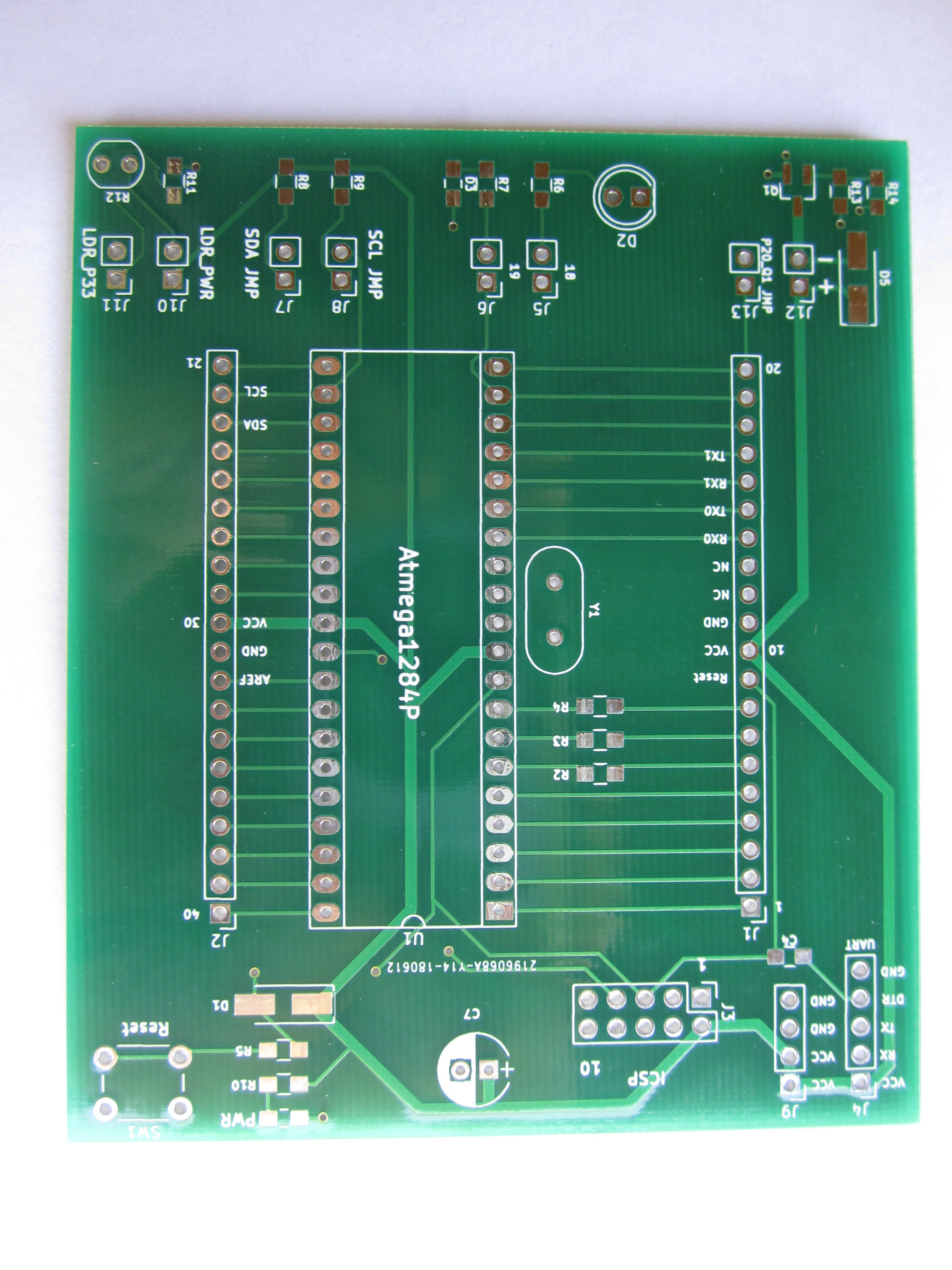
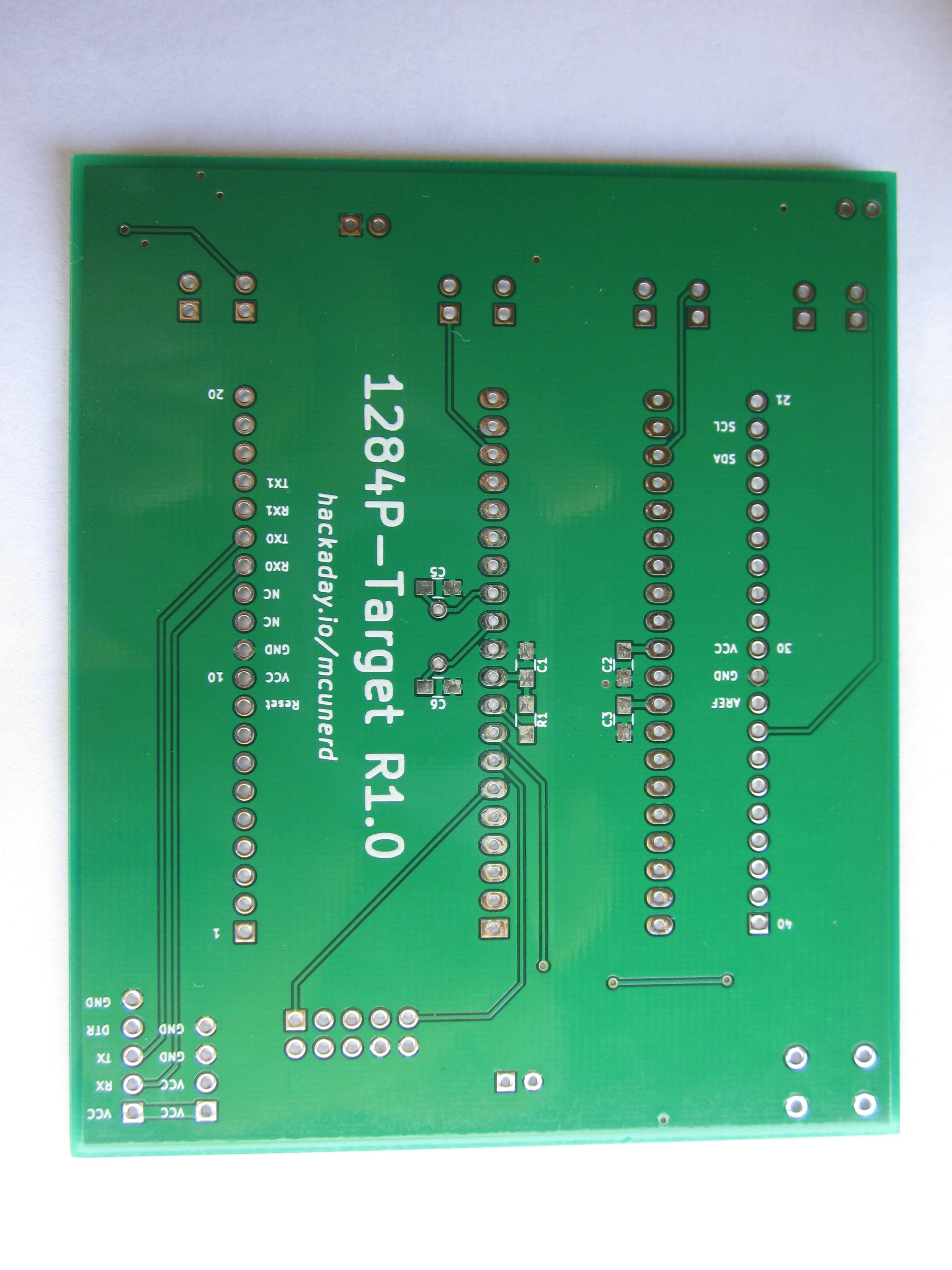
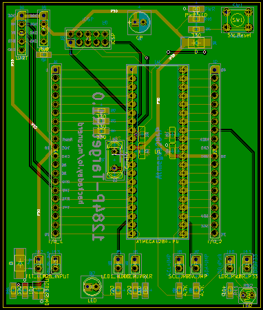
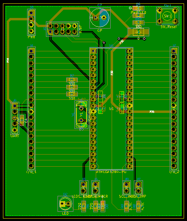
Planned features:

Pads to add a crystal

10-pin ICSP header

UART header

Reset button (about time I added one to a dev board)

a few I/O controllable LEDs

an option to add a 3-pin IR receiver 

1284p-TargetR1_1.zip

KiCad board files and Gerbers for the R1.1 board

x-zip-compressed - 482.12 kB - 10/15/2020 at 12:52

Download

1284p-TargetR1_0.zip

KiCad board files and Gerbers for the R1.0 board

x-zip-compressed - 201.29 kB - 04/18/2018 at 23:04

Download

  • Finally got around to uploading the newer board revision I did some ago

    mcu_nerd10/15/2020 at 13:31 0 comments

    Yup, it's been one of those to-do things for quite some time. I've finally gotten around to it.

    Summary of changes:

    added a voltage plane

    added a separate SPI header

    Added a separate I2C header

    consolidated a lot of the jumper pins to make life easier

    Parts list for the new board:

    kicad 5.0.2-1

    Resistors:

    3 10k ohm 0805
    5 330 ohm 0805
    2 220 ohm 0805
    2 4.7K ohm 0805
    1 1k ohm 0805

    LDR resistor through-hole
    Capacitors:

    4 .1uF 0805
    2 20pF 0805

    optional TH smooothing cap

    LEDs:
    2 0805 LEDs (one for power, another one controlled by an I/O pin)

    Pin headers(2.54mm):

    2 20-pin
    1 2-pin
    2 4-pin
    1 5-pin
    1 6-pin
    1 2x2-pin
    1 2x6-pin
    1 2x5-pin (recommend used shrouded socket)

    Other stuff:

    2 SS16 SMA diodes
    1 THT:SW_PUSH_6mm reset button
    40-pin socket for mcu
    HC49-U through-hole crystal (16MHz)

    for the transistor DMG2302UK or any mosfet/bipolar with a compatible pinout

  • After playing around with the board for awhile, a few other changes that I would make

    mcu_nerd08/29/2018 at 14:13 0 comments

    Overall, I think I didn't do a half-bad job on the board but there are a few more things that I would change in addition to a reader's suggestion of dedicated headers for I2C and SPI:

    Move the crystal and its capacitors a little further away from the socket to make it easier to install a ZIF socket.  While I don't swap out chips often, the Atmega1284P holds on for dear life which means considerable force is needed to remove the chip, which makes bending a pin or two a real possibility. 

    Add a jumper in series to the power LED.  When it comes to working with low-power projects and running it off of batteries,  the little bitty LED can consume quite a bit of power compared to everything else.  One could simply not solder in the LED, but this would be a more flexible solution.

    Combine many of the jumper headers. Soldering in a lot of 2-pin headers is a bit time consuming and more tricky the get them straight vs using one or a few larger headers.

    Possibly shrink down the board size. The fab that I used for this board (JLCPCB) quotes the same price for anything up to 10 x 10 cm, so unlike with other boards I've designed I didn't place as much emphasis on making everything compact as possible.  While it does give me quite a bit of room to easily add things on for future revisions, in it's current state it does mean it would cost considerably more to get it made at a fab that strictly charges by the square in or cm.

  • It came, got assembled, it works!

    mcu_nerd07/11/2018 at 14:26 0 comments

    The Saturday before last my PCBs arrived from JLCPCB.  I got the joy of getting out my soldering station and assembling everything.  It doesn't look like it would take too long but between being several months since I last used my soldering station, getting SMD components out of their packaging, orienting the resisters the "right" way (curse my OCD) , doing a mid-assembly cleaning with IPA, and having a few parts deciding to launch across the room. it took me around 3 hours.  It would really be nice to have a space for a dedicated bench vs having to invade to kitchen counters, but you can't have everything.

     I plugged in an Atmega1284P chip, connected my USBASP, used avrdude to check that it could communicate with the Atmega1284P, no response so I simply had to push it in slightly more and was able read it fine.   I plan to play around a bit more with the board this week.

    Again many thanks to all of you that liked my project that resulted in me getting the HaD prize seed funding to pay to get the boards made.  I'm not currently employed (I do side jobs when I get the opportunity), so I have to watch my spending.

  • More changes made

    mcu_nerd04/18/2018 at 23:03 0 comments

    I've been messing with the board design a bit more. I've added an small N-channel MOSFET to the board and also rearranged a few things including the placement of the UART header.  Thanks to all of the likes that I've received, I have the funding to get this board made.  

  • N-channel MOSFET recommendation?

    mcu_nerd03/28/2018 at 13:10 0 comments

    Been thinking about what else I can add to the board.  Does anyone have any recommendations for an inexpensive general purpose N-channel logic level MOSFETfor controlling larger things?  I'd preferably would want one in a surface-mount package so it would sit flat against the board.

  • What features/design changes would you like to see?

    mcu_nerd03/20/2018 at 03:22 0 comments

    I've been working on the design tonight and came up with a basic layout. I did leave off the IR receiver at least for now (need to find a suitable footprint for it in KiCad.)  I added the option to connect pull-ups for the SDA and SCL pins. The board does look rather a bit empty and plain.  If anyone has any features/design change suggestions, be sure to comment.

View all 6 project logs

Enjoy this project?

Share

Discussions

open-plc-com wrote 07/12/2018 at 03:24 point

Everything has already been invented ... Take protoboard-uni (any) https://hackaday.io/project/29527-protoboard-uni, if necessary, combine with the https://hackaday.io/project/159068-protoboard-uni-as-arduino-shield. Solder the required connectors, parts, etc. The result can be placed in a DIN-rail enclosure box.

  Are you sure? yes | no

Peabody1929 wrote 07/11/2018 at 16:32 point

I would like to suggest adding a dedicated header for SPI and I2C.  I realize these signals are available on the existing headers, but it would be easier to just plug on a harness.

  Are you sure? yes | no

mcu_nerd wrote 07/14/2018 at 00:49 point

Thanks for the suggestion! Will do if I do a board revision (probably be a while before it happens.)

  Are you sure? yes | no

David H Haffner Sr wrote 03/28/2018 at 15:24 point

Love this project, this is 1 of my favorite chip's to work with :)

  Are you sure? yes | no

Similar Projects

Does this project spark your interest?

Become a member to follow this project and never miss any updates