The "stages" of this project are:
Smartphone connected to wifi
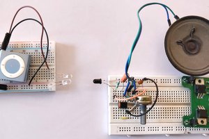
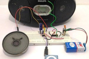
Old audio amplifier (pc speakers or bluetooth speaker)
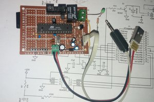
Comparator and relay circuit (made by you!)
The objective is to energize the relay to switch anything (in this case to connect the two wires that signal the garage door opener)
 Emilio P.G. Ficara
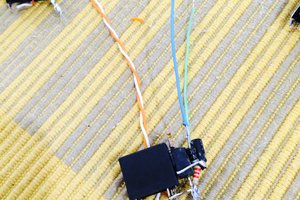
 GNbyma