0%
0%
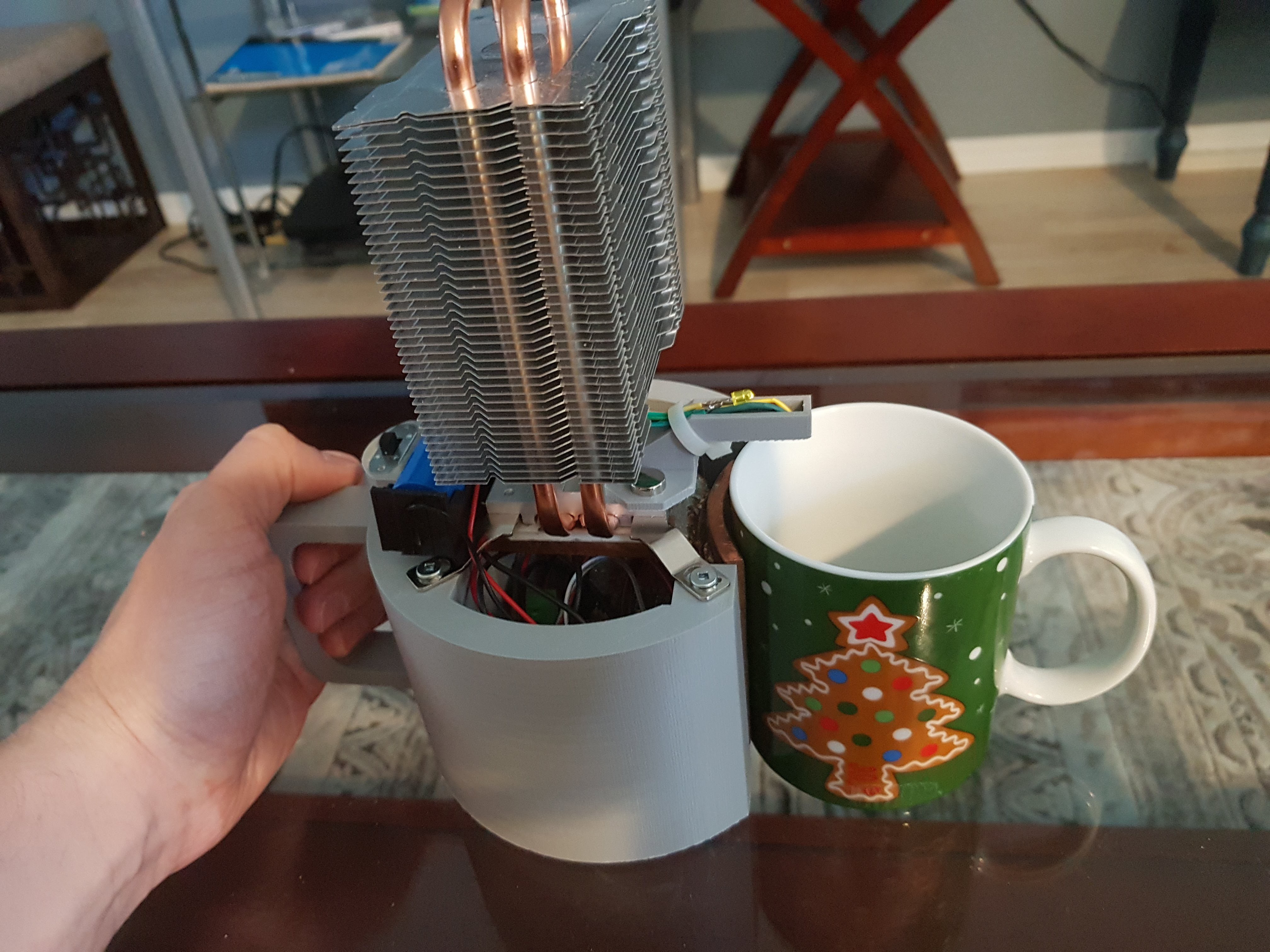
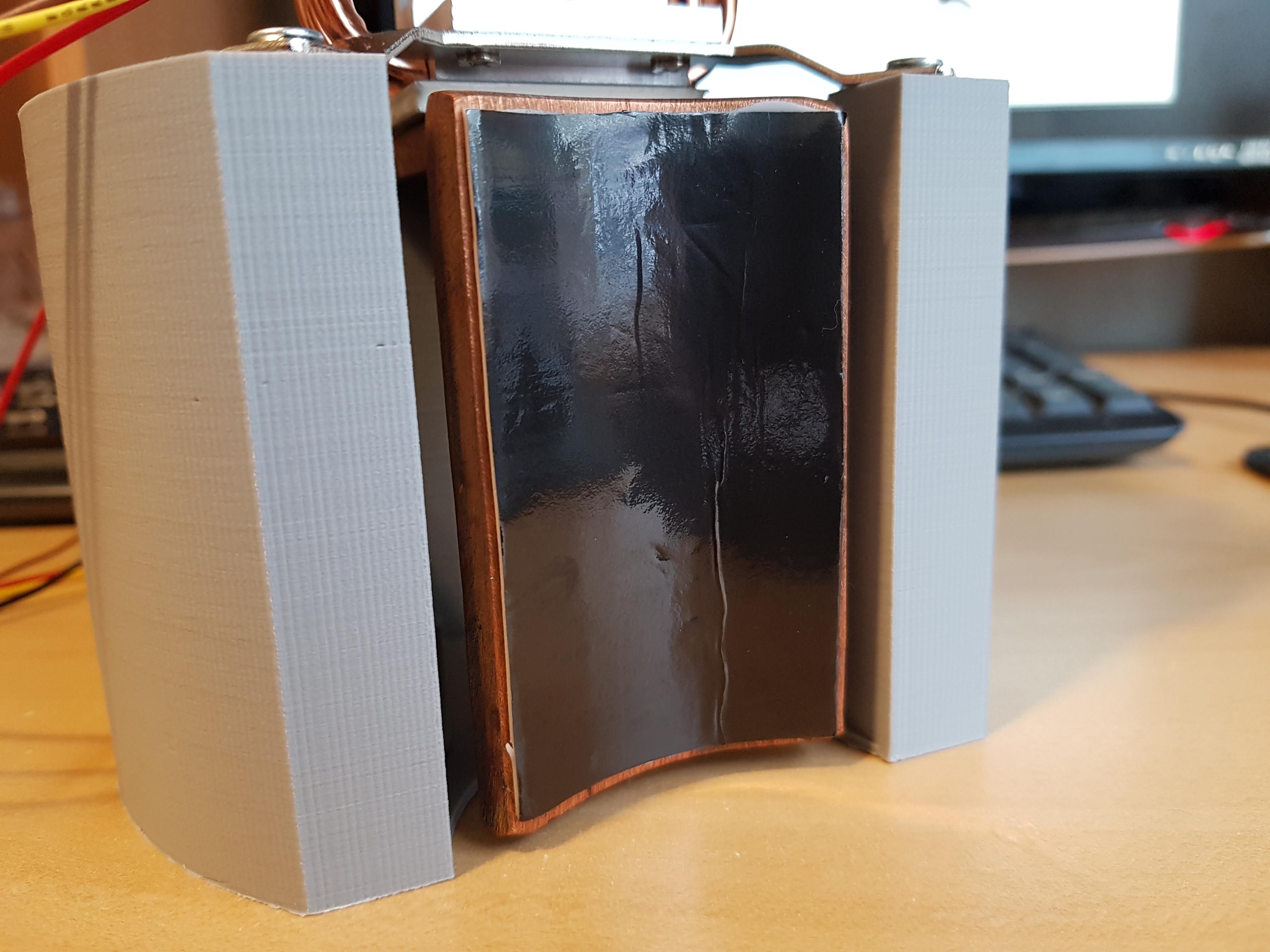
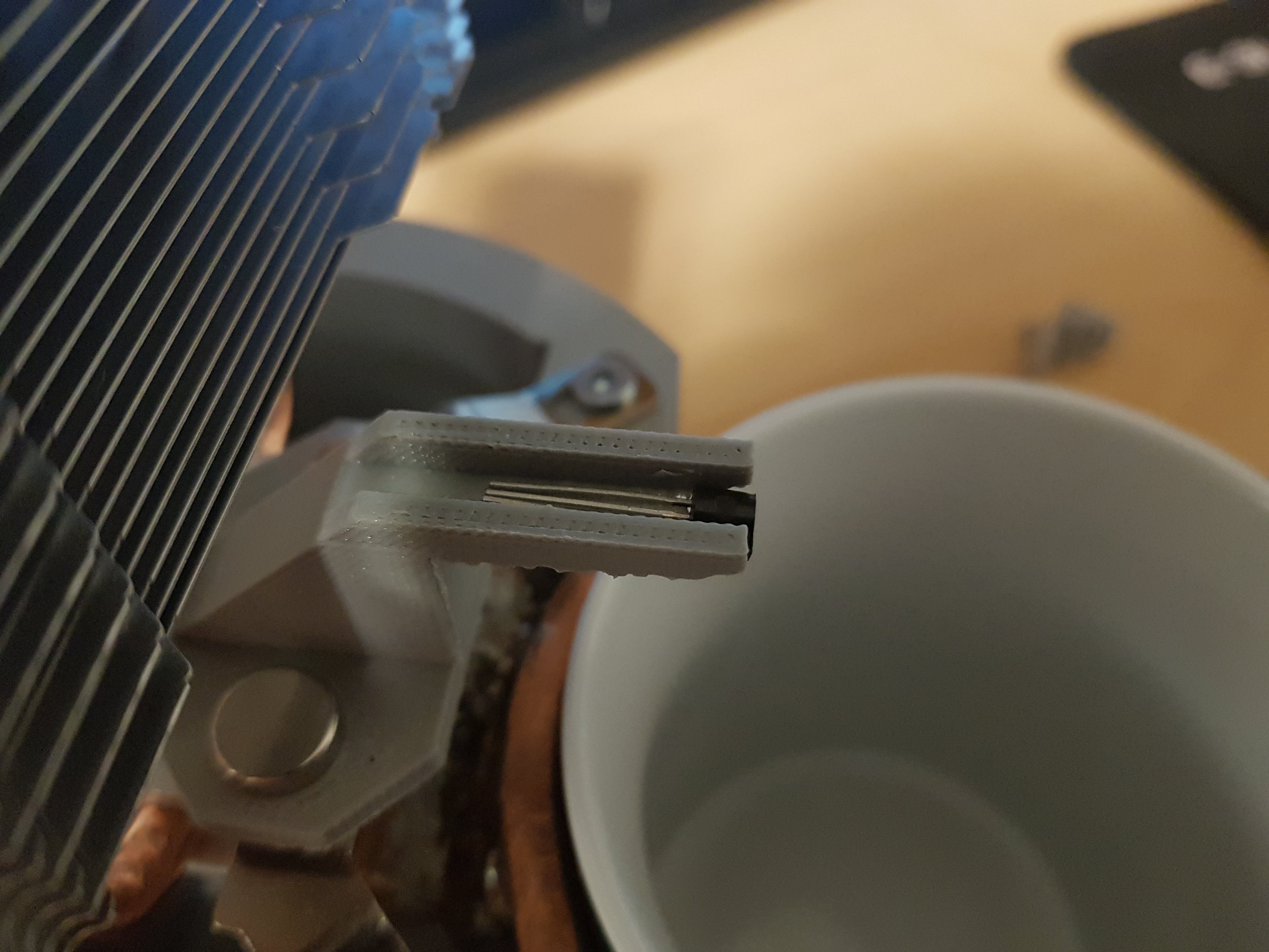
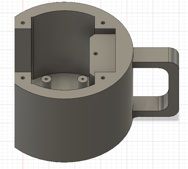
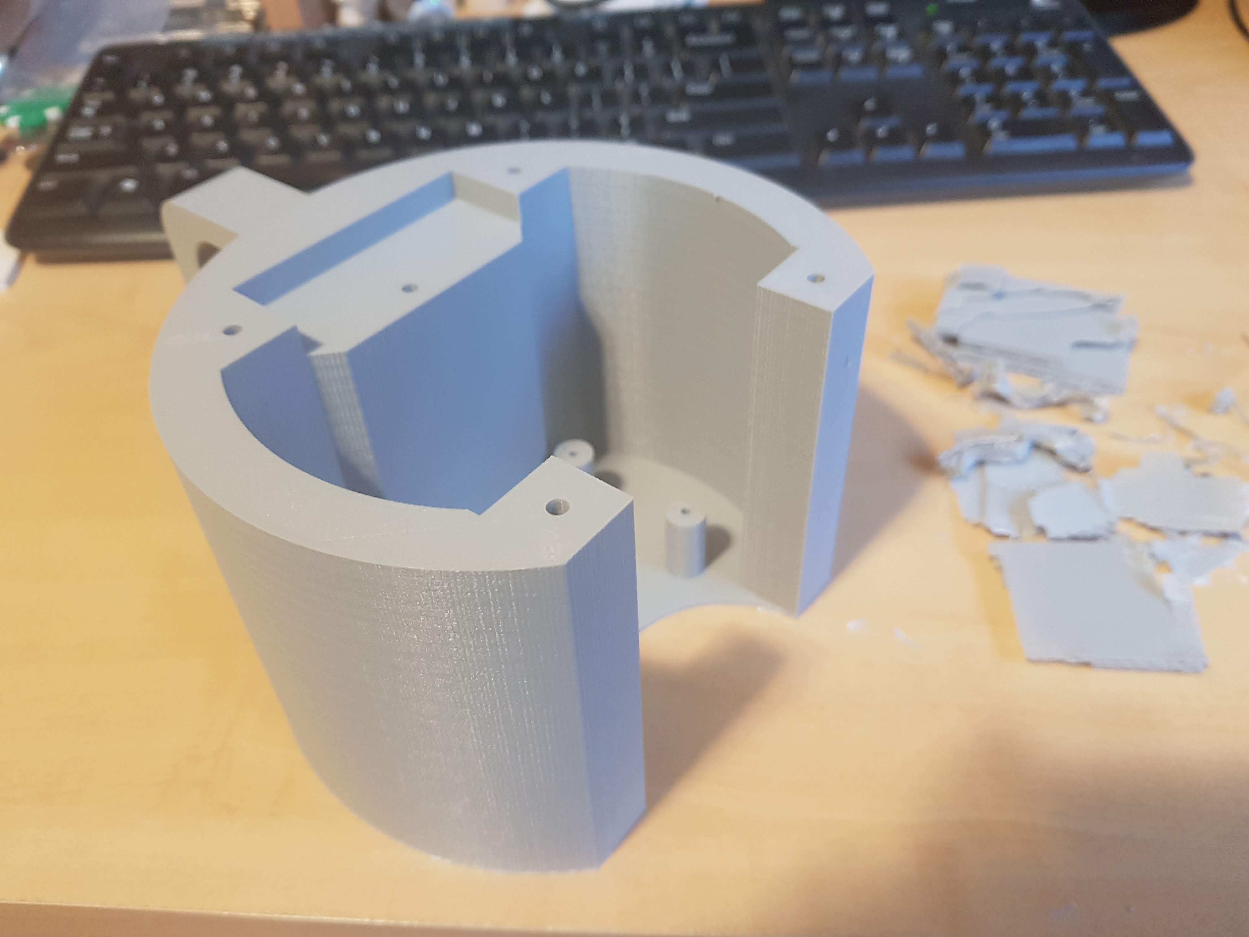
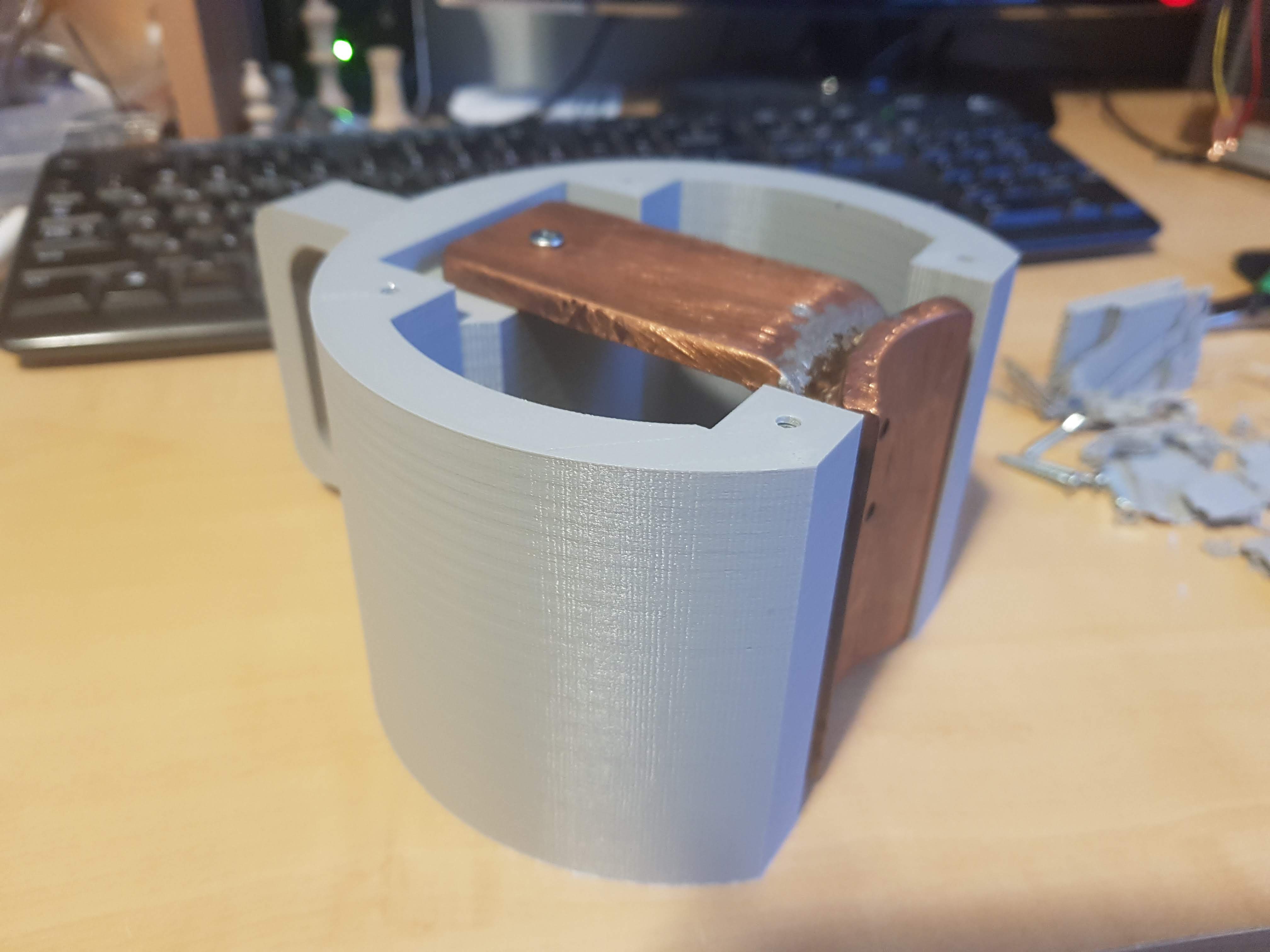
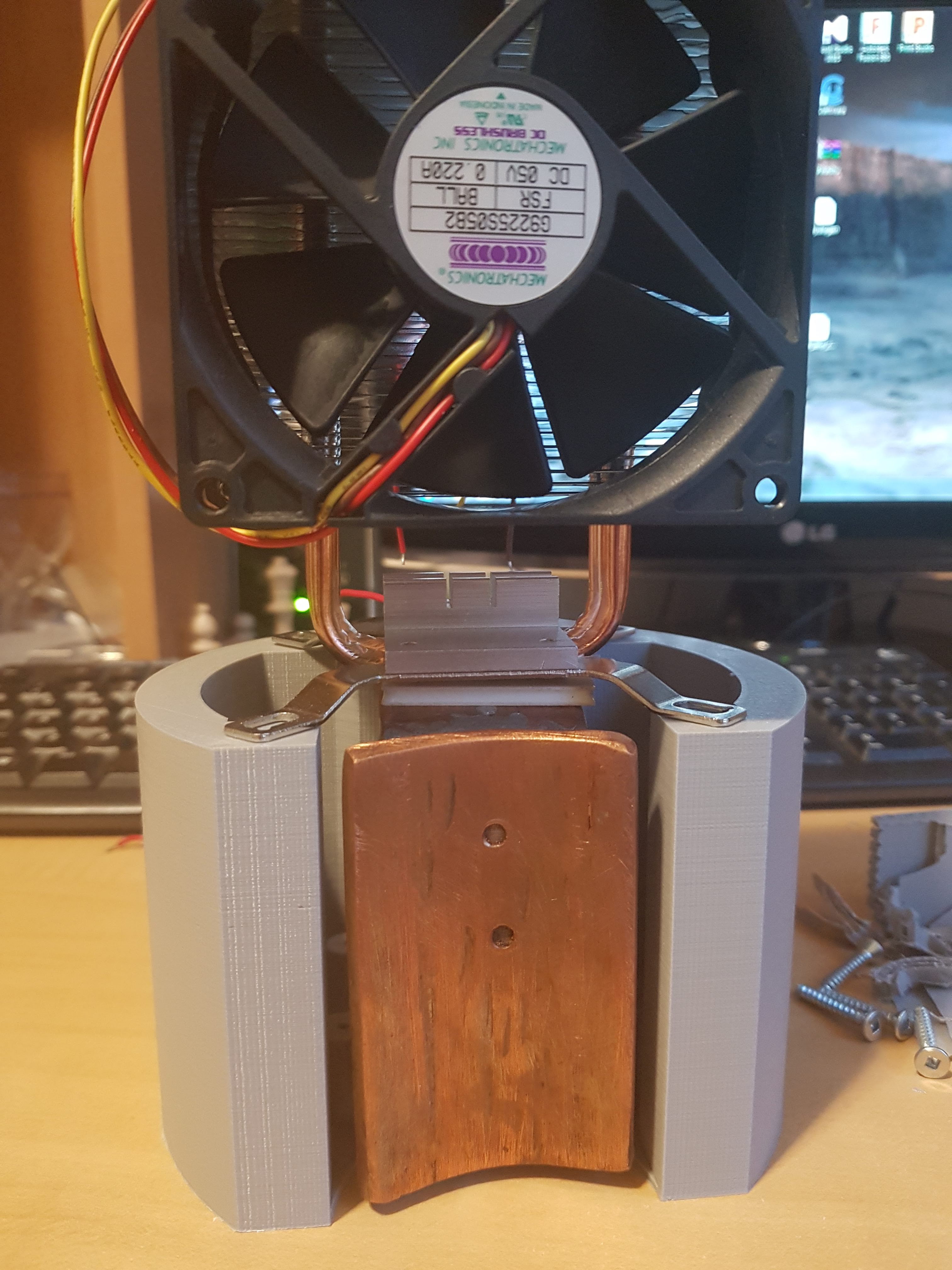
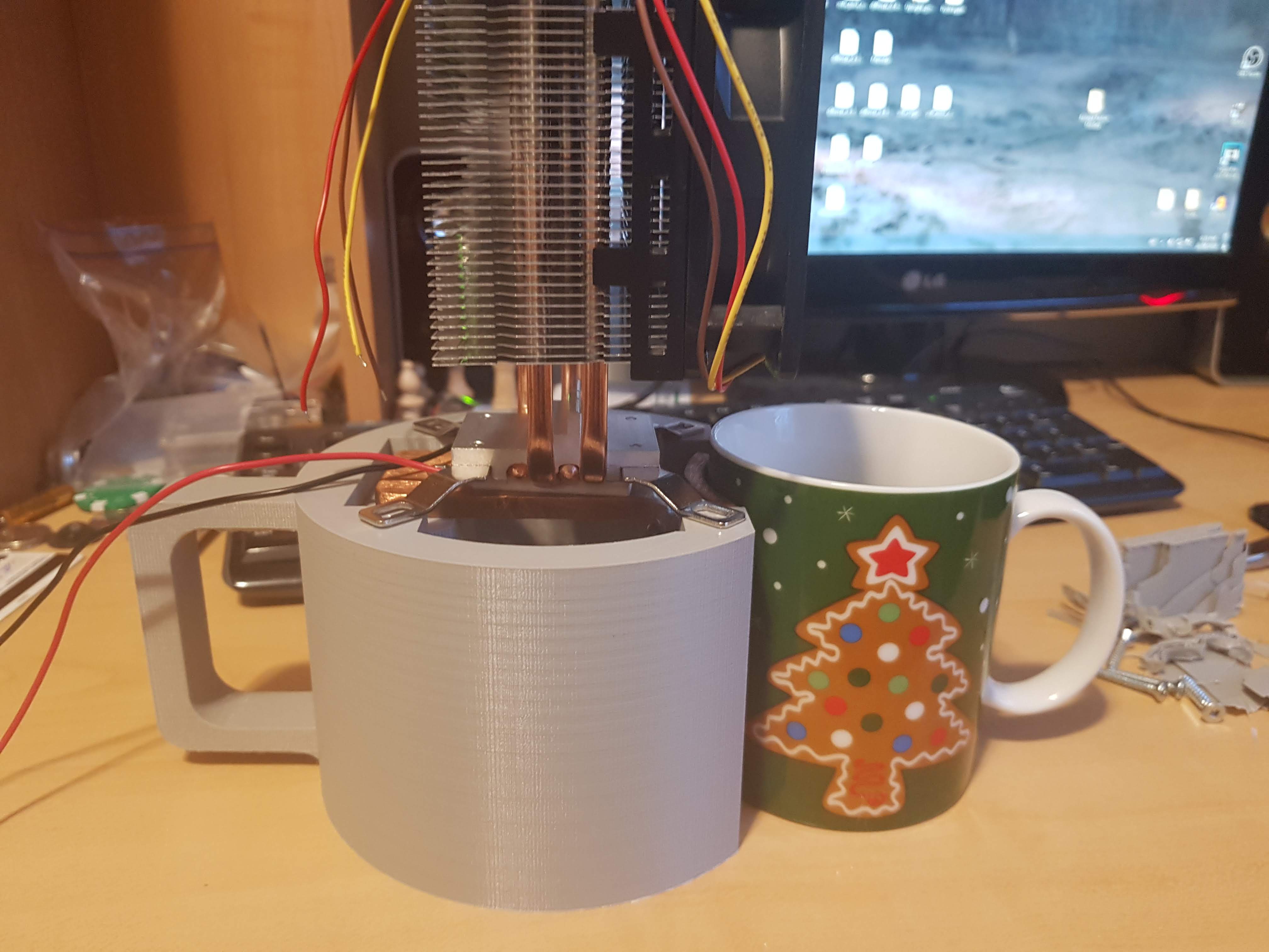
Coffee/Tea Cooling Buddy
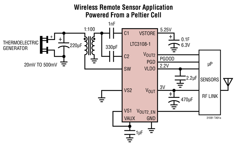
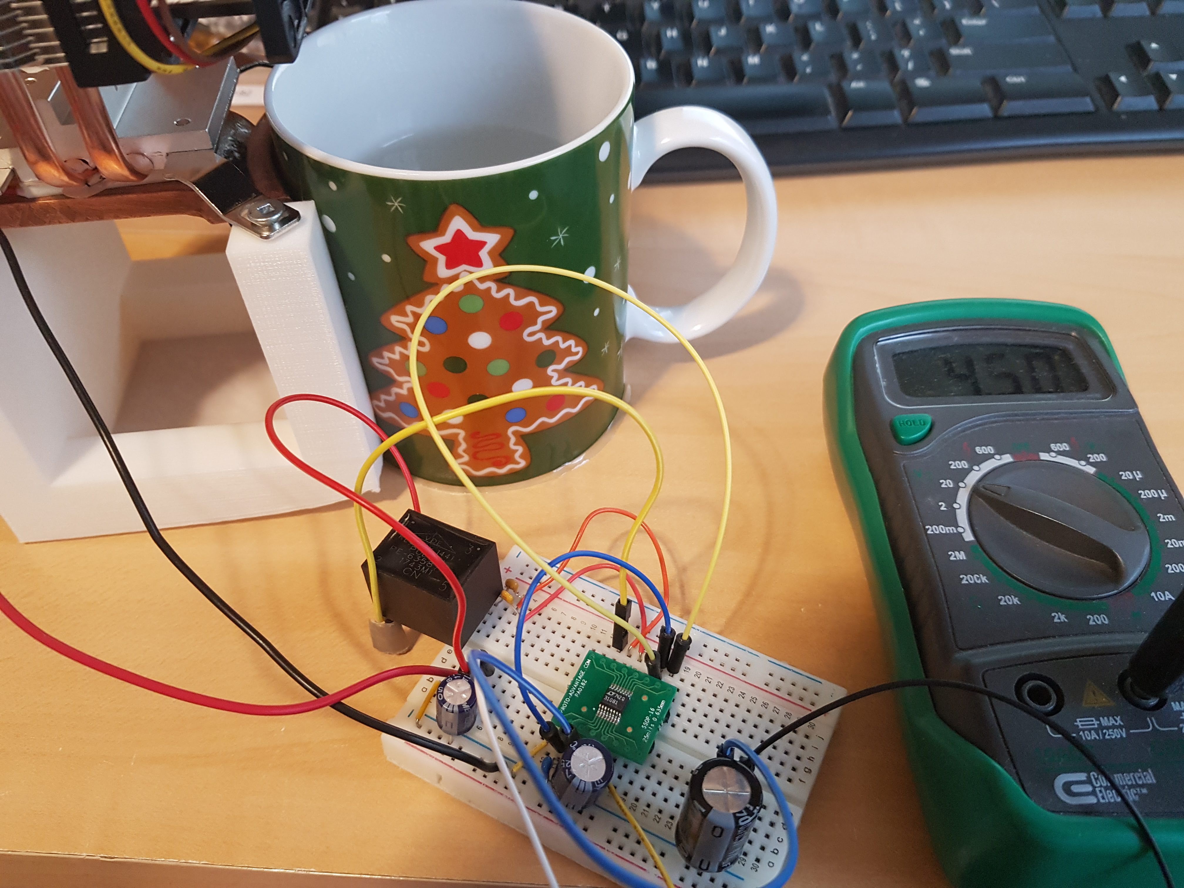
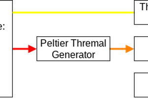
Monitor the temperature of your drink and know when it reaches the perfect temperature. Even generates a tiny bit of electricity too!
 Scott Clandinin
Become a Hackaday.io member
Already have an account? Log in.
Just one more thing
To make the experience fit your profile, pick a username and tell us what interests you.
Pick an awesome username
hackaday.io/
Your profile's URL: hackaday.io/username. Max 25 alphanumeric characters.
Pick a few interests
Projects that share your interests
People that share your interests


 Patrick Van Oosterwijck
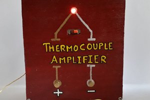
 Rudraksha Vegad
 greg
greg
I like the idea, but how about a nitinol thermal engine or some other thermal process, rather than converting to electricity (sure to be inefficient)?