 Scott Clandinin
In order to alert the user when their drink is cooled down, I need to roughly know the temperature. The major constraint here is running off low power, so I need an analog only solution as I won't be using a microcontroller. If I could avoid it I want to find a solution where I don't have to stick a temperature probe into my drink.
Thermistor Design
When searching for a device to monitor temperature I was first drawn to a thermistor. The analog output and low power draw were desirable. The idea was to monitor the ambient temperature above the cup. I knew it wouldn't be very accurate, but that the temperature above the drink should roughly correlate with the temperature of the liquid. I was very wrong.
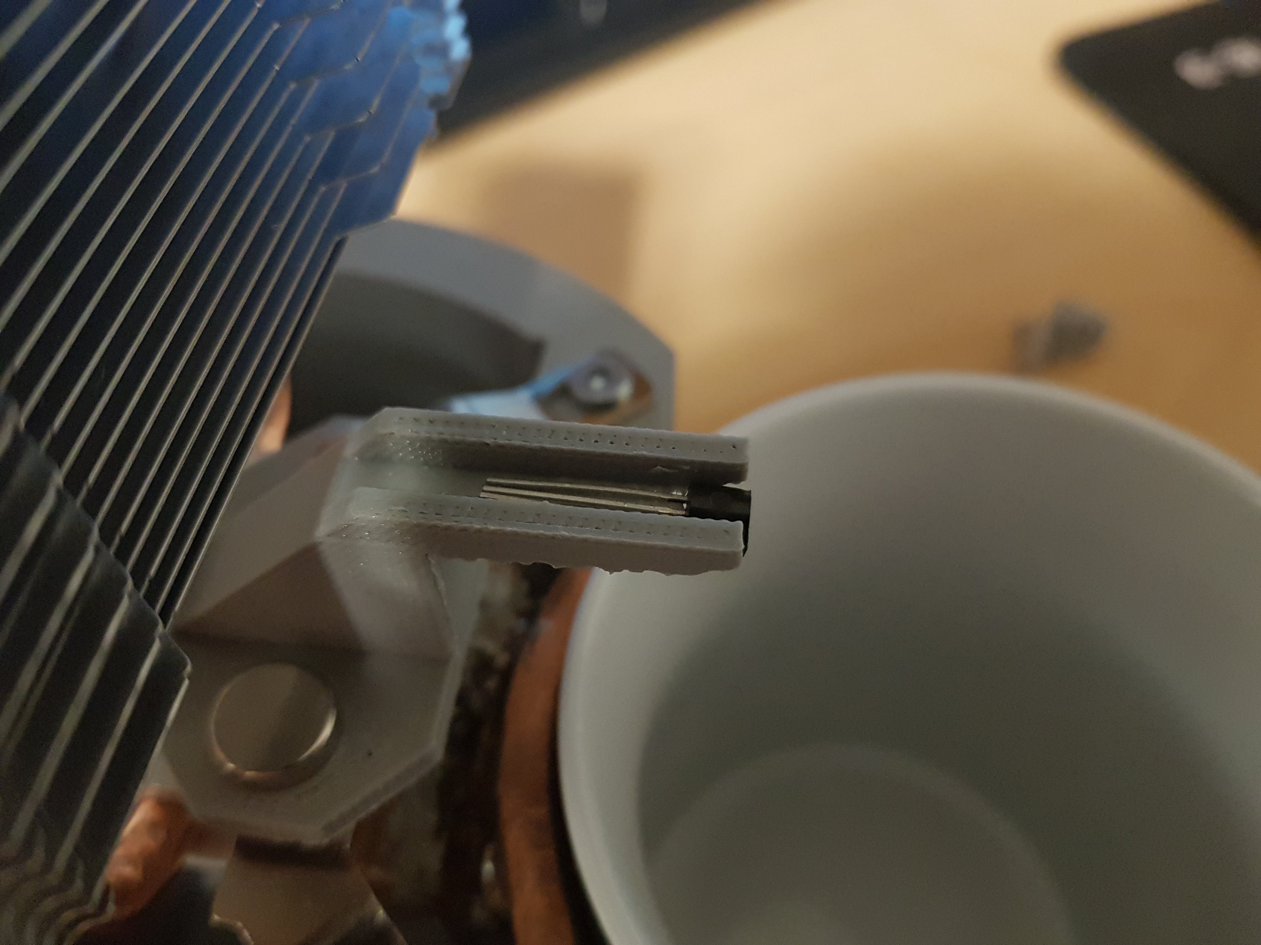
I 3D printed a housing to hold the thermistor above the cup. Space for two magnets was made on the housing so this can be loosely attached to the heat sink base.
It was a pretty big failure all around. The first downside is that it doesn't begin at the proper temperature as the air below it slowly begins to warm up. This would make it more difficult to know when the proper temperature is reached, as it rises above the trigger point, where the goal of this is to trigger when it falls below that temperature.
The second downside is the effect of airflow on the sensor. Changing air currents would dramatically change the temperature sensed. This means that a person blowing on their drink could trick my system into thinking it had cooled down all the way.
The third downside, and the real killer of this idea is that it didn't correspond at all to the liquid temperature. The ambient temperature would continue to rise while the temperature of the drink began to fall. Up to a certain point the ambient temperature would begin to fall, but in an undesirable point of time.
Themopile Design
I did some more research and realized an option was out there to use a themopile IR temperature sensor. I found a part specifically for IR temperature measurement. The ZTP-135SR sensor has a built-in thermopile for IR sensing as well as a thermistor to monitor the ambient temperature. The output of the thermopile is dependent on the ambient temperature, so it is necessary to know the ambient temperature in order to know the temperature of the surface being measured. The datasheet for the above sensor didn't explain much, but I found a great resource from Hamamatsu on thermal detectors.
This explains a bit of the theory of operation, as well as shows some application circuits which I based my design on. The output of a thermopile is determined as follows.
Where To is the object temperature, Ta is the ambient temperature, S is the sensitivity coefficient, and B is a coefficient of about 4. S and B are determined by measurement and are based on the individual sensor. As my use for it doesn't involve any calcluations, all I need to know is the voltage that corresponds to 60 degrees C (which can be done experimentally).
I built the below circuit as recommended by the Hamamatsu document above.
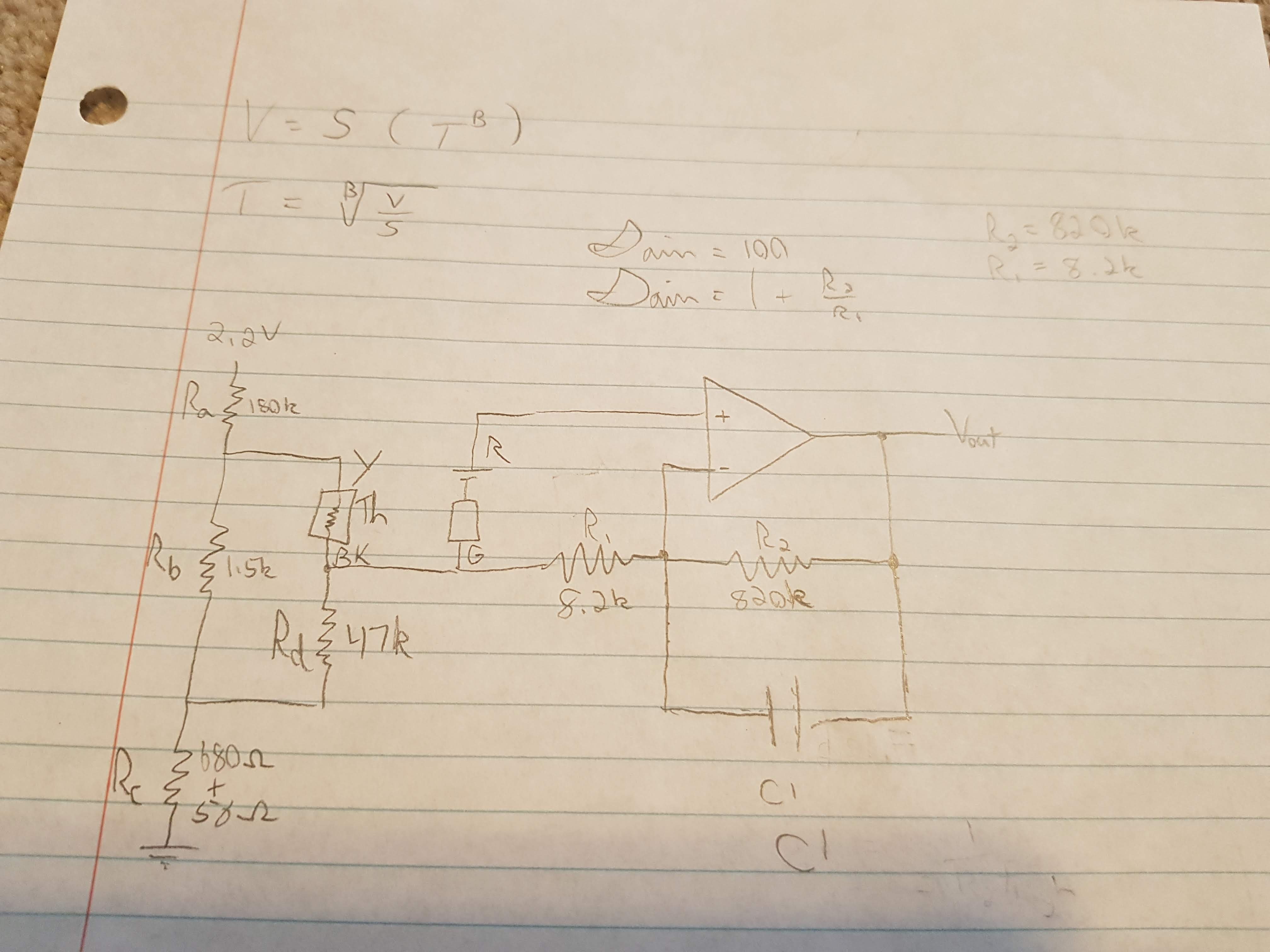
This thermopile only produces only about -5mV to 10.5mV, so an amplifier is need to get this into a more measureable value. The resistor network on the left serves to linearize the thermistor output. This can feed into the negative feedback of the amplifier to minimize the effect of changes in ambient temperature (which are a big issue for this design). This circuit aims to use the 2.2V low voltage dropout regulator of the harvesting chip. Through the equations derived in the document, my values were as follows. I used approximations in my test circuit, but will try to get closer for the final design.
Ra = 164kΩ
Rb = 1.46kΩ
Rc = 730Ω
Rd = 45.6kΩ
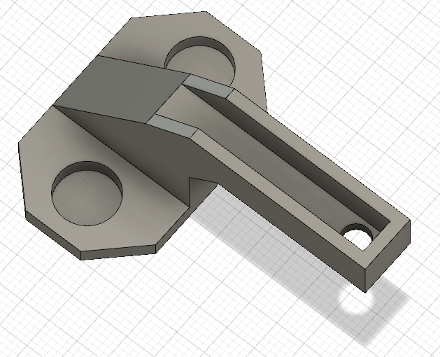
I designed the thermopile housing similar to the thermistor one before.
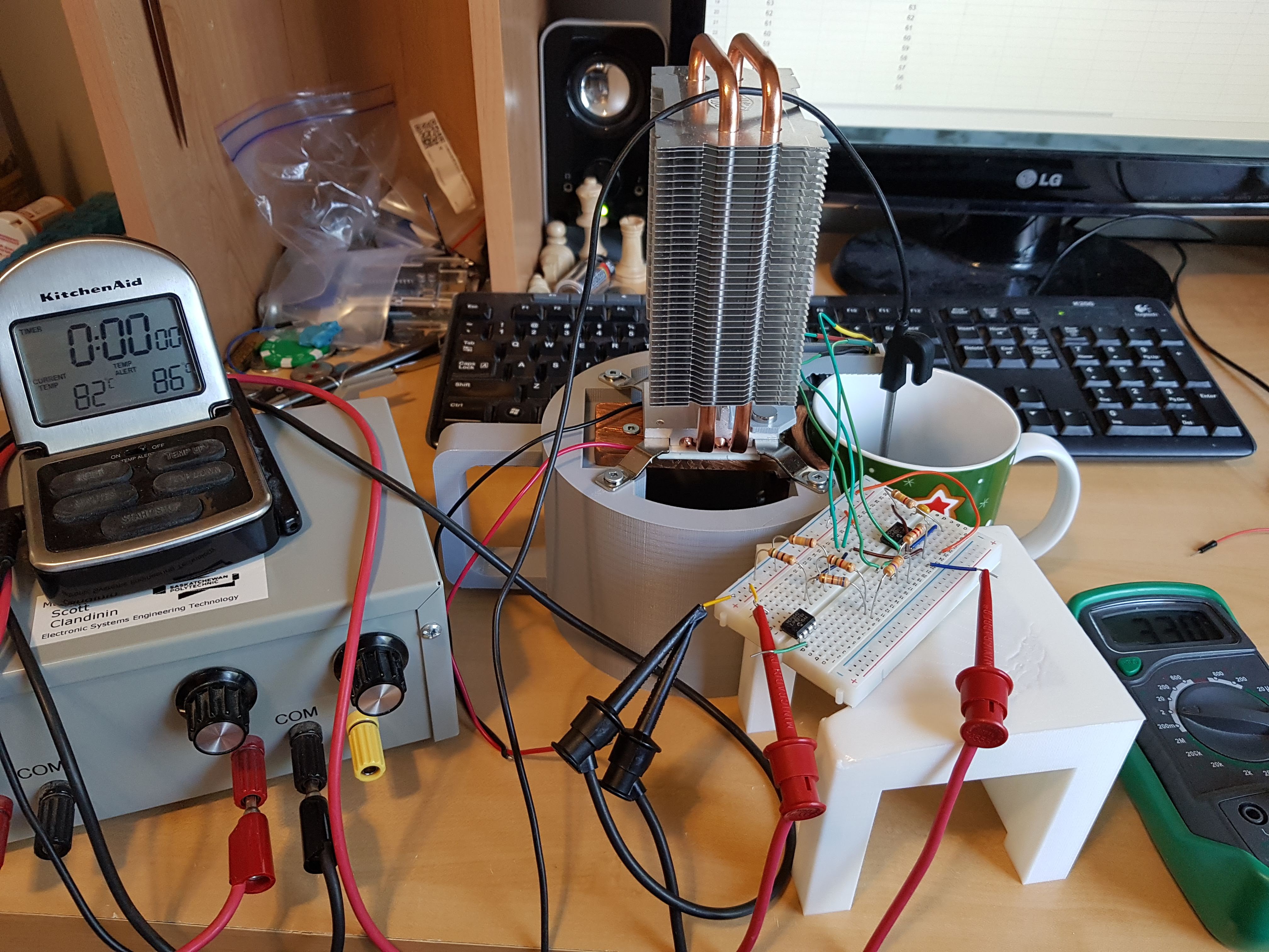
I tested the circuit with a regulated 2.2V supply in case the harvesting circuit could not supply adequate power. I did two separate tests. One set of measurements with the cup 75% filled, and one set with the cup 90% filled. I wanted to know the proximity to the sensor had.
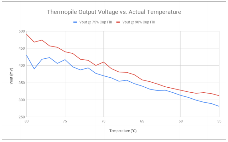
Measurements were taken at each degree interval. A proper datalogger would show the actual data fluctuations, but this gives a good idea of the trend and confirms it is reasonably linear.
There is an obvious offset introduced here, but it isn't too bad, and can hopefully be fixed by getting closer resistance values to the values calculated. Measurements in the range between 80°C and 70°C do not show the whole story, as between this range there was great fluctuation in voltage, sometimes as large as 30-50mV. This is very likely caused by varying air currents caused by the evaporating water. Blowing on the cup would have a similar effect.
Near the 65°C to 55°C rage the output was a lot more stable, typically only fluctuating as much as 5mVto 10mV. It was often stable within 2mV to 3mV, yielding pretty stable results. This was a successful test and is accurate enough for the purposes of my design.
At 60°C I had outputs of 313mV and 328mV. Some tightening up of the resistor values should help with the offset, but my trigger voltage will likely be around 320mV. This voltage level will be what determines when the LED begins to flash.
Discussions
Become a Hackaday.io Member
Create an account to leave a comment. Already have an account? Log In.