 Scott Clandinin
Designing the circuit was an evolving process partially based on trial and error.
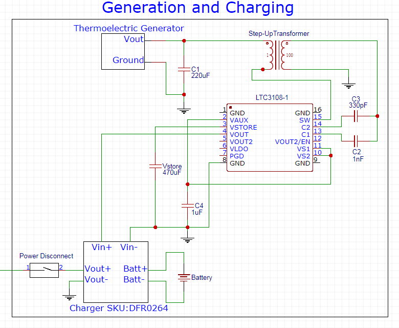
Energy Harvester - LTC3108-1
In the end I decided to stick with the LTC3108-1. It is able to boost the low TEG voltage up to around 5V (though any attempt to put a load on dramatically drops the voltage.
Charger - Module Based on CN3083
I purchased a battery charging module that is able to control incoming power to charge the battery without overdriving and dropping the voltage too much. There were two LEDs on the module that indicated charging and charged states that I removed.
The output of the module powers all of the temperature monitoring circuitry, LED, and fan. I have a disconnect before all of that so that everything can be shut off while the harvester is still generating electricity.
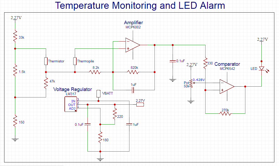
Voltage Regulator - LM317
The voltage regulator was a late addition to the party. I initially had everything running off the battery voltage, but realized that as the battery gradually dropped, the calculations and calibrations would cause inaccuracy. In order to keep everything operating the same regardless of battery life was to keep the voltage exactly the same. I used a voltage of 2.27V to keep enough difference in Vin and Vout to keep the regulator constant. I calculated for around 2.2V, but got an output of 2.27V with common resistor values, so I made my calculations based off that number.
Thermopile Temperature Sensor - ZTP-135SR
The left side of the circuit is required to linearize the thermistor that is measuring the ambient energy. This doesn't do a great job, as the output isn't very linear with ambient temperature change, but it is good enough for this project (especially given the short timeline before the deadline).
Amplifier - MCP6002
The thermopile itself does not require any input voltage, but gives off a small voltage based on the amount of infrared radiation. Since it is so small I've used an amplifier to amplify the signal by a factor of 100.
Comparator - MCP6542
I used a non-inverting comparator to trigger the output to go high when the desired value was reached. With the new supply voltage of 2.27V, the output of the thermopile amplifier was about 0.428V at 60 degrees C. I could have used the inverting comparator to have the output go high once the temperature was reached, but for simplicity just had the device sink the current rather than source it.
Discussions
Become a Hackaday.io Member
Create an account to leave a comment. Already have an account? Log In.
Might want to read section 4.3 of your MCP6002 datasheet as opamp in general (like 99%) do not like driving a high capacitive load.
Are you sure? yes | no
There are much better regulators than old 317 - much lower drop out and quiescent current.
e.g. MCP1700 https://www.microchip.com/wwwproducts/en/MCP1700 You can get 2.5V ones
In your application, you should look into getting a voltage reference source instead of a regulator - less changes in value over temperature (TEMCO) and they are low power too.
https://www.microchip.com/design-centers/analog/data-converter/voltage-references
Are you sure? yes | no
Cool, thanks for the tips! Appreciate it.
Are you sure? yes | no