Following steps are executed by this robotic system to achieve object detection and following. First, object is extracted using image processing method. Second, errors such as heading angle error and distance error between detected object and the robot are calculated. Third, controllers are designed for minimizing these errors.
A. Image Processing Method
In this method, a color-based object detection algorithm is developed for the Kinect camera sensor. AForge.NET C# framework has been used to provide useful set of image processing filters and tools designed for developing image processing algorithm [10]. The method is executed as below.
1) With the help of Kinect camera, both color (RGB ) and depth information are collected. In the development of this algorithm, the first step is to detect specified colored object and then get its position and dimension. Finally, the object is located in the image.
2) The simplest object detection is achieved by performing color filtering on the Kinect RGB images. The color filtering process filters pixels inside or outside of specified RGB color range and fills the rest with specified color (black color is used in this paper ). In this process, only object of the interested color is kept and all the rest are removed out.
3) Now, the next step is to find out coordinates of interested colored object. This is done by using 'Blob counter' tool, which counts and extracts stand alone objects in images using connected components algorithm [10]. The connected component algorithm treats all pixels with values less than or equal to 'background threshold' as background, but pixels with higher values are treated as object's pixels. However, 'Blob counter' tool works with grayscale images, so, gray scaling is applied on the images before using this tool.
4) Last step is to locate the detected object in the image. Once the object is located, we get the coordinates (X,Y) of the centre of object.
Note that, the desired range of area for an object is chosen to be from 1m to 1.2m. The reference distance for an object is chosen as 1.1m as shown in Figure 1. The distance between an object and the robot is obtained using Kinect depth map. If the object is located 1.2m or further, the robot will go towards forward direction. If the object is placed less than 1m, the robot will go towards backward direction. And, if the object is within this range, the robot will stop. Figure 2 shows an image frame having detected object with its center coordinates (X,Y) within a desired area.
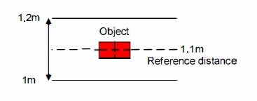
Figure 1 Desired range of area for an object
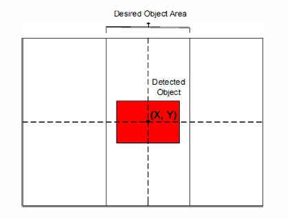 Figure 2 Image showing a detected object within desired area
B. Error Measurement

Figure 3 Image showing detected object with its center coordinates (X1,Y1) outside a desired area
1) Heading angle error:
Consider an object is detected in the right corner of an image frame with its center coordinates (X1, Y1) outside a desired object area as shown in Figure 3. To make the robot (quadcopter) turn towards detected object, it should change its current angular position to a desired angular position to achieve object following. Therefore, a heading angle error e is defined as,
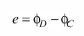
where φD is the desired angular position of robot and φc is the current angular position of robot as shown in Figure 4.
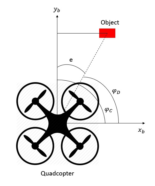
Figure 4 Heading angle error definitions
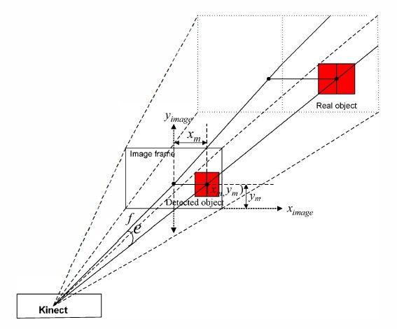
Figure 5 shows an extended view of a heading angle error, e, from the Kinect camera with detected object in an image frame having its center coordinates as (xm,ym) pixels.
According to the image principle explained in [4] and [11], the heading angle error e between the center of detected object and the center of RGB image is given by,

where a is the pixel size of the color image with detected object. f is the focal length of Kinect camera and n is the pixel difference between the center of detected object and the center of RGB image frame.
In this project, only the heading angle is considered for error measurement. Therefore, n in the equation above can be replaced by xm. Thus, a heading angle error can be calculated as,

2) Distance Error
The distance error can be defined as the difference of a reference distance between an object and the robot and a current distance between them. The distance between an object and the robot can be obtained by a depth map using Kinect camera sensor.
The distance error can be defined from Figure 6. The current distance between an object and the robot is yb and the reference distance between them is yD. The distance error is defined as,

Reference:
[4] G. Xing, S. Tian, H. Sun, W.Liu, H. Liu, "People-following system design for mobile robots using Kinect sensor," in Proc. of 2013 25th Chinese Control and Decision Conference (CCDC), 2013, pp. 3190-3194.
[11] C. D. Herrera, J. Kanna1a, J. Heikkila, "Accurate and practical calibration of depth and color camera pair," in Proc. of 14th Intemational Conference on Computer Analysis of Images and Patterns, 2011, pp. 437-445.
A. V. Gulalkari, G. Hoang, H. K. Kim, S. B. Kim, P. S. Pratama and B. H. Jun, "Object Following Control of Six-legged Robot Using KInect Camera," ICACCI, South Korea, 2014.
Discussions
Become a Hackaday.io Member
Create an account to leave a comment. Already have an account? Log In.