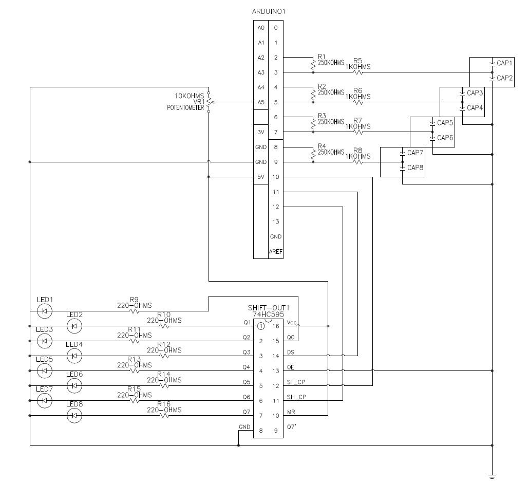
The proof of concept code is straightforward and simple. Any function that you could want, there exists an arduino library. Just google and ye shall receive.
Capacative Sensor: http://playground.arduino.cc/Main/CapacitiveSensor?from=Main.CapSense
Analog input (Potentometer for sensor threshold value):https://www.arduino.cc/en/Tutorial/AnalogInput
Shift out( 3 pins to drive up to 8 LEDs ): https://www.arduino.cc/en/Tutorial/ShiftOut
All that i did was take these code repositories and put them together into one program. The only changes were to modify the pins used as needed. A few notes: Pins 0 and 1 are used if you declare any Serial commands. Pin 13 as an output will turn on an onboard LED. The analog input pins can be addressed as digital inputs where Analog in 0-5 are digital inputs 14-20.
https://cdn.hackaday.io/files/9636412266624/ProofOfConceptClean.zip
Once we have this code together we can monitor the signals in the arduino Serial Monitor/Plotter.
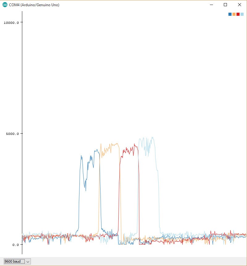
You may notice that as the program continues to run the values recognized by your sensors will slowly drift upwards. Pressing the reset button temporarily fixes the problem. This is because the signal is "Floating" or un-grounded. Adding a capacitor from signal to ground keeps the sensor from building up charge when there is no input signal. I was confident this was the issue, i did not purchase any capacitors. My plan was to build a capacitor using a second layer of grounded chicken wire in the prototype design.
Once we are happy with the signal as seen in the serial monitor we are ready to take the next big step. Adding the code repository to make the Arduino a controller. To do this, we comment out all of the Serial commands. (it messes with the visualizer. )
https://github.com/AlanChatham/UnoJoy
Download the Master Zip. Upload the demo Aurduino code. \UnoJoy-master\UnoJoy\UnoJoyArduinoSample. Then run this application \UnoJoy-master\UnoJoy\UnoJoyProcessingVisualizer You don't the drivers for the visualizer. We combine the code so that the Capacitive Sensor initiates a button press in the visualizer.
https://cdn.hackaday.io/files/9636412266624/PrototypeClean.zip
Once we have achieved success with the visualizer there are a few more steps to convert the Arduino to recognize as a USB controller. (Don't worry, you can convert modes back and forth.)
You can follow the ReadMe in the Master Zip, but i ran into an issue on windows 8.
Installed this http://www.atmel.com/tools/FLIP.aspx
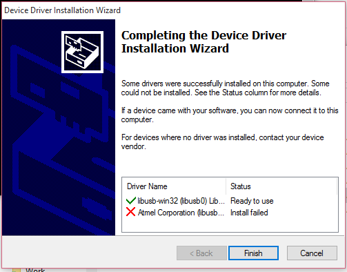
Installed this /drivers/WindowsUnoJoyDriverInstaller.exe
Got this error.
There is a trick to activating DFU mode on the Arduino board.
Power the controller.
Jumper the two pins closest to the USB module. This is Communication reset for the smaller chip.
Remove this jumper then jumper the two pins farthest from the USB Module. You are now in DFU mode.
You will see the communication lights change on the board.
You will see the device name change in the device manager.
When i ran
\UnoJoy-master\UnoJoy\TurnIntoAJoystick.bat
I ran into this error "AtLibUsbDfu.dll not found."
The solution was to manually update the driver for the Amtel chip in DFU mode from the device manager.
The driver is found here.
C:\Program Files (x86)\Atmel\Flip 3.4.7\usb\atmel_usb_dfu.inf
Swedish YouTube video where I found the fix: https://ww.youtube.com/watch?v=KQ9BjKjGnIc
Once you have run \UnoJoy-master\UnoJoy\TurnIntoAJoystick.bat you need to unplug and re-plug in the Arduino.
There we have it! The capacitive sensor recognizes as a joypad input on the PC. I verified this by attempting to map the Capacitive sensors to an emulator Nestopia, or Stepmania.
Discussions
Become a Hackaday.io Member
Create an account to leave a comment. Already have an account? Log In.