 Nickolas Peter
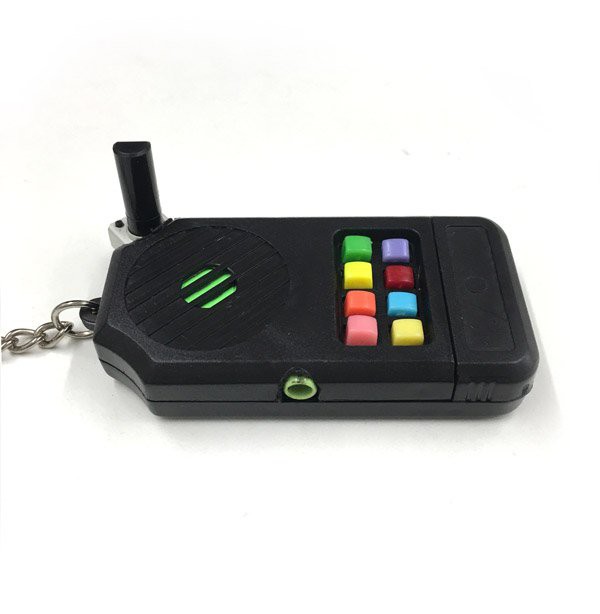
Remember those 80s keychains with the laser noises? Some were called the Executor, The Echo Keyller, Thriller, and some other names. This was my first real circuit bending project (that's why I called it Patient Alpha) and might be of interest to those looking to circuit bend this thing or something like it.
These are the steps I took to replace the resistor in the RC circuit with a pot, then added a headphone out jack. This thing really screams.
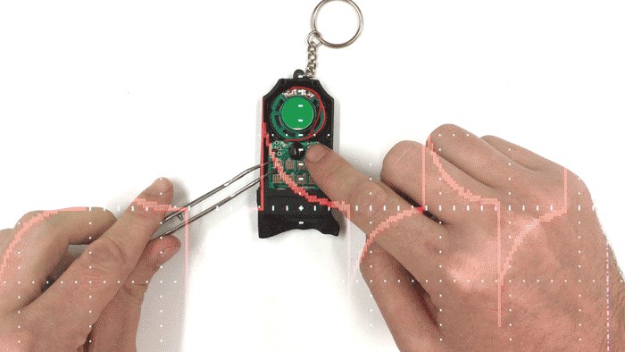
So if you're working with a battery powered device, you can find tweakable parts on a board by rubbing it with a licked finger (this might be obvious to some, but I had no idea :)
You don't want to do this with a device plugged into a wall. This is a quick before/after video:
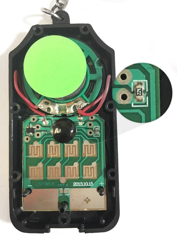
This board is super simple, and the only thing that made it squak was the resistor on the top right as I triggered the button pads with the tweezers (pin to ground). It's labeled 224, and for those really starting out, that means 22 times 10 to the power of 4 = 220,000 or 220 kilo ohms.
So I thought why not replace it with a variable resistor (potentiometer).
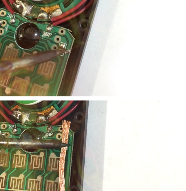
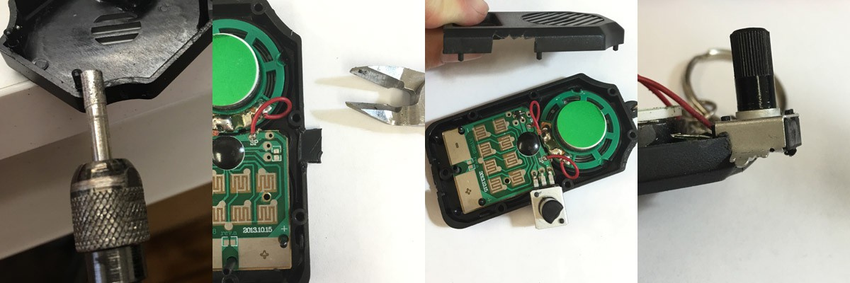
First remove the original resistor by heating it up and using some solder wick to absorb the remaining solder.
It's kind of amazingly convenient that there are extra pads right next to the pot and on the power traces on this 2013 reissue of the keychain. The original 1989 version had no such thing:
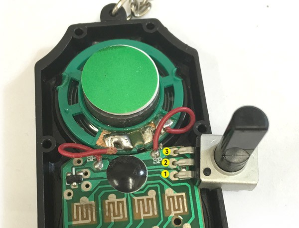
I labeled the pads so it's easier to talk about. Here's the funny part, using the 100k pot on 1 and 2 (which are the original resistor pads) acts in a way you might expect. Approaching 0 resistance the sound gets faster and faster (at 0, it zappy/and shorts, which is not good). As you turn to 100k it slows down. But at 100k it's still about twice as fast as 220k, which makes sense. So 1 and 2 are kind of "fast" to "superfast"/zappy.
So here's the weird part, and where my knowledge starts to suffer, plugging the third pin of the same pot into pad 3 (which is power), widens the range a LOT! At the higher resistances, there's even a really slow spot (think slow motion). And there is a lot of dead space at the bottom. Which might just be because the whole circuit is getting shorted, and it'll just drain the battery (not sure, open to comments). But this 1,2,3 combo works if you want to give it a shot. 1 and 2 I call the "Easy Peasy" mod and it's just fine, but the range could be wider, and the zero short can be a problem (like if you leave it at zero, your battery will just die).
-------------------------------
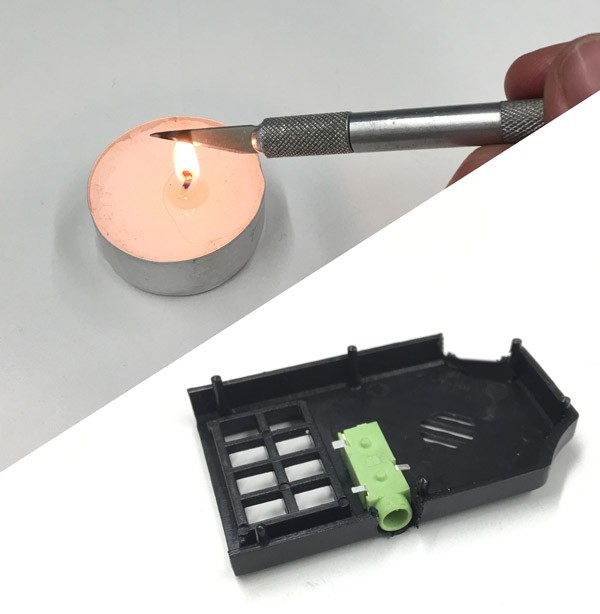
Cutting the Enclosure
A quick interlude about actually getting the pot in the case. I think the top right shoulder of the enclosure is a pretty good spot (press buttons with your left hand, twist knob with right hand), but it could go anywhere really. You can dremel it, which was my favorite at first, you can hotknife it (which takes its own kind of finesse, have to be smooth and fast and precise), or you can just snip it little by little with some snippers, which honestly became my favorite because it's the most peaceful.
You just have to not get too ambitious at once and take little bites in a sawtooth fashion. If you go for too much at once, you risk cracking the case, which isn't too big a deal because you can glue it together, and the area around the pot will be covered up if you use a sizeable knob (which is the most fun).
----------------------------------------------
The Right Amount of Resistance
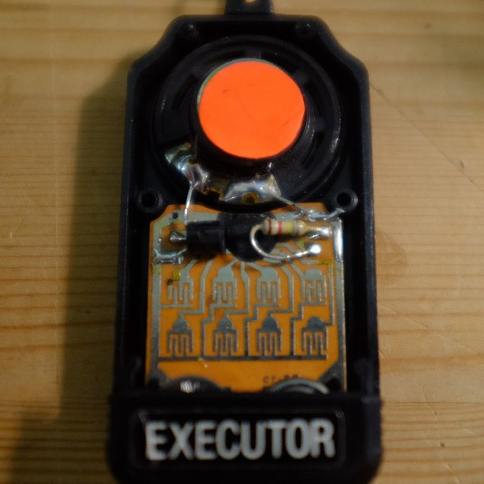
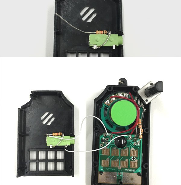
The best experience in my opinion is when there's a wide range of speed and no dead zones. So here's the combo that works for me every time (but I'm sure there's a ton more things that could happen). I raised the ground with a 10k and a 10 ohm (just to remember easily and avoid using a wire. Then the to power resistor was a matter of trial and error and 20k provided the most range without any deadness.
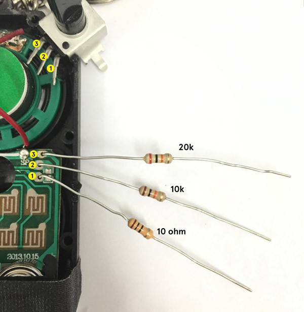
I tend to solder the resistors in place then bend them upwards. I'd recommend snipping them shorter than in the picture so that the resistors end up being at approximately the midpoint between the board pads and resistor terminals (next to the speaker). See below. And you want to make sure none of the leads cross. I've gotten pretty good at configuring the resistors so they don't touch, but the first few times I used electric tape to keep them separate and everything neat.

Then you want to cut an opening in the front face before putting it on. And make sure you don't cut the wrong side since it's upside down (might be obvious but I've made that mistake :)
And boom! Knob mod complete! Headphone out coming up!

-------------------------------
Headphone Out Jack
What makes this thing more fun? Plugging it into an big ass amp! Maybe add some pedals for some extra sauce and you're flying! So let's get on with it.
Some of the readers probably know this – stereo audio connectors have three parts: tip, ring, and sleeve (TRS).
Sleeve is to ground, Tip is left audio channel, and Ring is right. Mono connectors are just Tip and Sleeve (TS). I figured this thing might be fun with stereo headphones too, so might as well split the audio into both channels give it a stereo out (or dual mono to be specific).
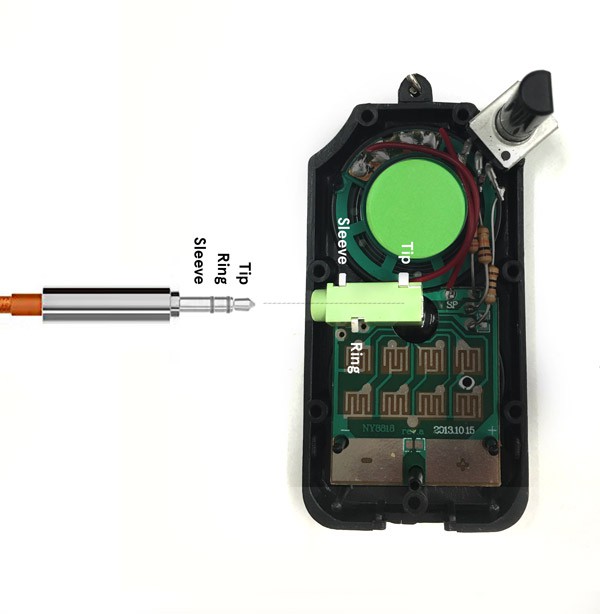
I personally find this left facing spot the best location (fits nicely). I originally wanted to stick it out the top left shoulder so it would be somewhat symmetrical to the potentiometer, but it would require some extra finagling. Here's a diagram of the connections I made:
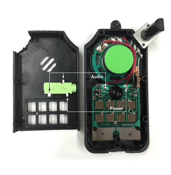
I just went ahead and connected the left side of the speaker (between speaker and transistor amp) to the two audio channels, and the right side to the sleeve and it worked. Some headphone jacks have an extra tab on the rear for surface mounting, so I snipped that off to keep confusion down. Just to be sure what is what, I stuck a male to male headphone cable in the jack and used a multimeter to check TRS against the pins on terminals on the jack.
 Try to get the smallest headphone jack, the one in the picture has the same thickness as the front part of the case, so it just fits nicely. You can use whatever you want to cut the hole. A Dremel tool with a diameter approximately the same size as the jack makes for a neat round hole, hot knife works, but if you have the patience, I think snippers are the most zen anyway.
 WARNING: if you wire up the terminals directly, the headphone out will be LOUD!! Like ear-blasting loud, which is fine if you'll be plugging it into a device, but just not your ears :) So I use a 1k resistor between the board and Tip and Ring. I found it easiest to use the resistor to connect Tip and Ring together, with the resistor between the jack and the board. You can always stick the resistor on the board, etc, but what's important is that the signal comes out of the board, through the resistor, then split into left and right audio channel.
NOTE: this doesn't disable the speaker, so the sound comes out both the speaker and the jack. Disconnect the speaker if you want this to be a headphone out only device, or use a headphone jack that includes a switch that would interrupt the speaker circuit (I'll have to try this later myself).
Then put the case back together, careful with those buttons (the most annoying part of this whole thing, they literally go flying everywhere if you're not careful :) and boom! Super tweaky noisemaker with headphone out!
A tiny bit of history – For the last two years, I've been curating a series of art shows in the Cambridge, MA area called Curious Sound Objects, which are a blast. And I really wanted to get something out there that people could have fun with anywhere, and maybe even support the shows financially in a little way. If you're curious about the shows, or want to get a kit of all these parts, check out www.curioussoundobjects.com
-Nick