 shlonkin
Goal: To develop a music teaching aid that provides audio and visual cues as well as instant feedback about the student's performance.
When the student plays an incorrect note they will see what note they played in relation to the one they were supposed to play. The student would know which direction and how far they need to move the instrument to reach the desired note. It will make learning new songs more fun for the class and easier for the teacher.
Why does this project matter? It will provide a new educational tool that a school will actually use. It will improve music education and make learning to play harmonica more fun for kids. Also, since everything will be open source and completely documented, it will enable other teachers to construct similar devices and modify the design to work with other instruments.
Here is an outline of the device:
Functionally:
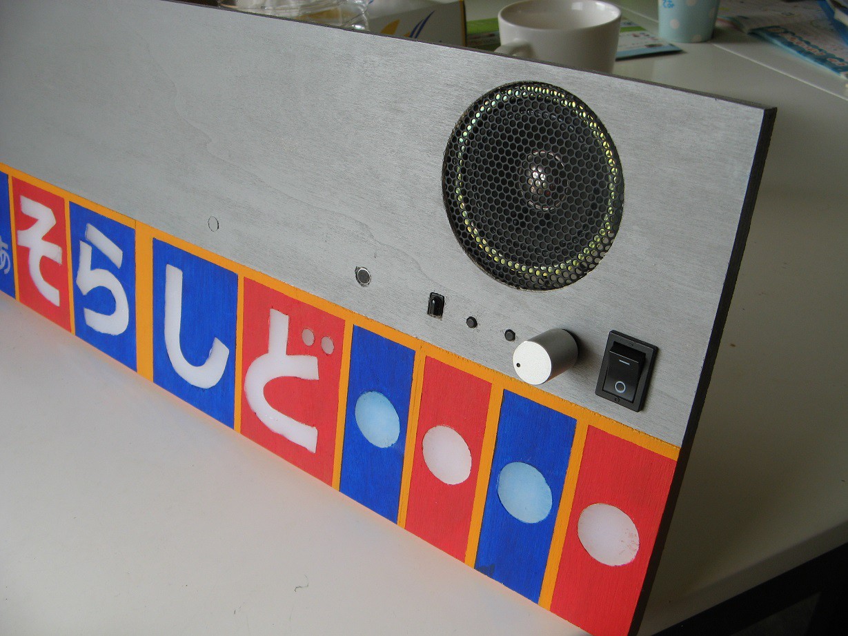
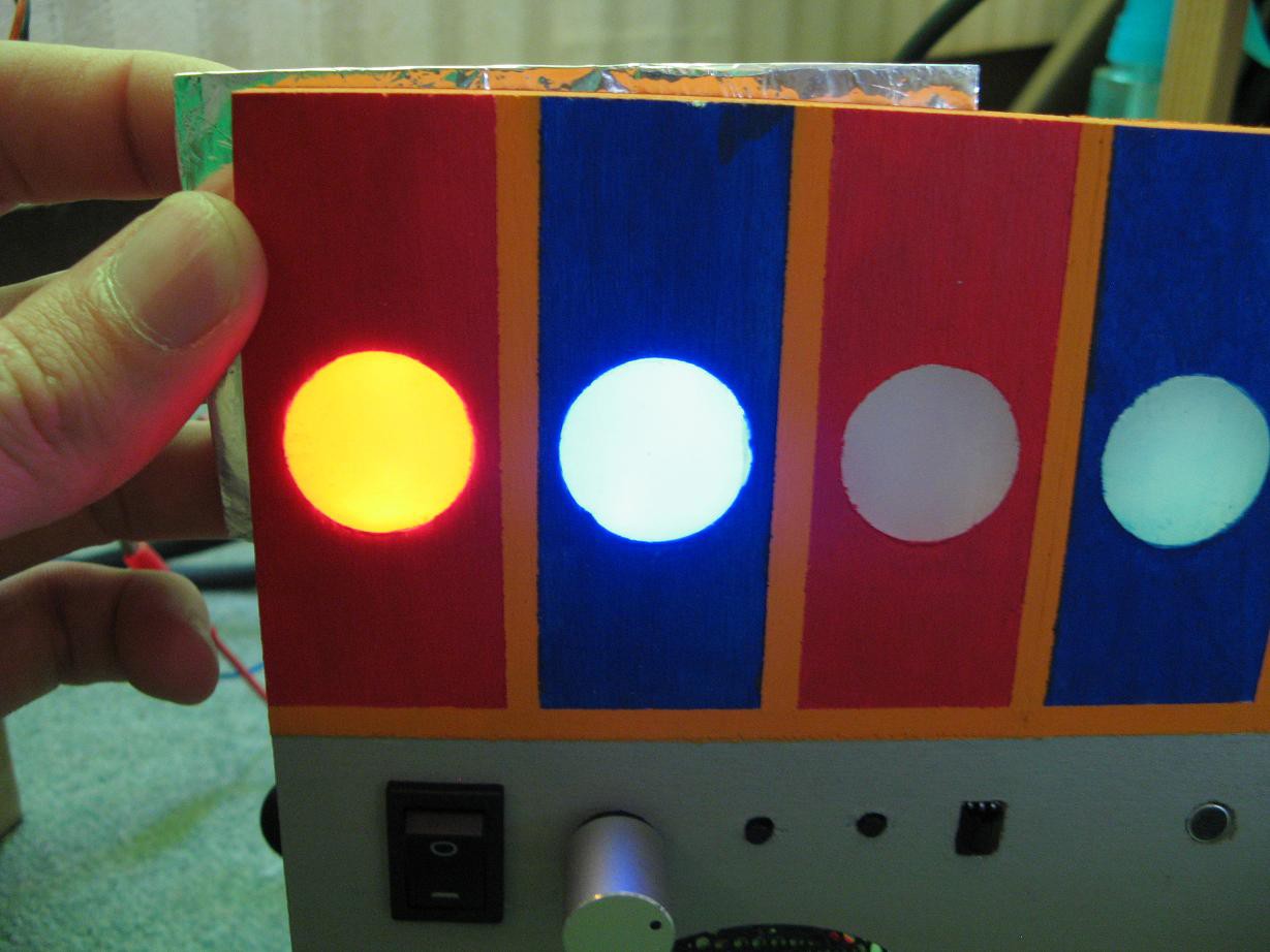
- Plays harmonica notes while lighting up the corresponding part of the harmonica either red(exhale) or blue(inhale).
- Notes can be played on a small remote keyboard.
- Has a microphone to listen to students play. The sound is analyzed to determine what notes are being played and the corresponding notes are illuminated.
- It can record and play back songs free of noise by playing samples(MIDI style).
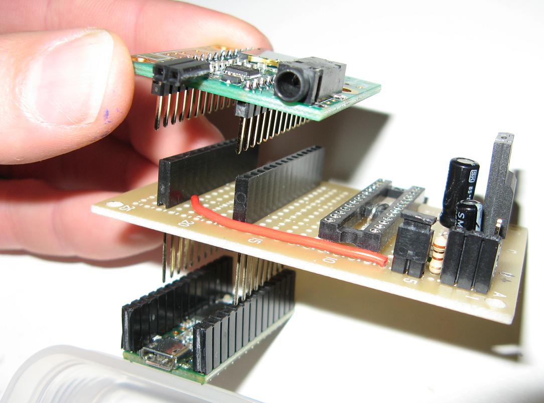
Electronically:
- Based on a Teensy3.2 with audio adapter board
- Red or blue LEDs for each note.
- An ATMega328 handling LEDs and IR input.
- Audio power amplifier(HT82V739) and speaker.
- A simple remote keyboard using IR.
- Microphone connected directly to audio board.
- An SD card contains sound samples and recorded songs.
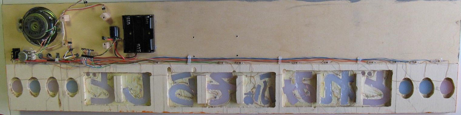
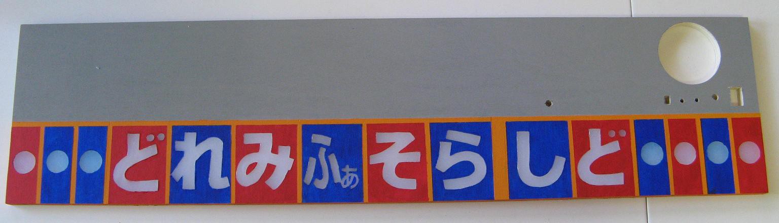
Structurally:
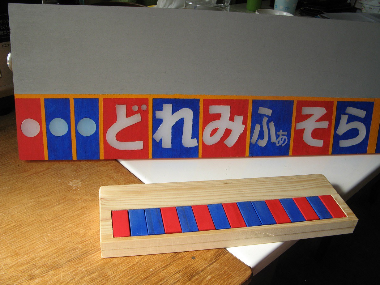
- It will be a long plywood board, 72cm x 18cm, representing a large harmonica.
- The notes will be colored red for exhale, blue for inhale.
- Each note will have individually controlled illumination.
- The large YAMAHA logo is there because that's what the real harmonicas look like so the kids know if the harmonica is upside down (It is not sponsored by YAMAHA, though that would be awesome).
- The electronics will be mounted on the back, probably in polypropylene folded and welded into a box(Stay tuned for that log as it is a handy trick).
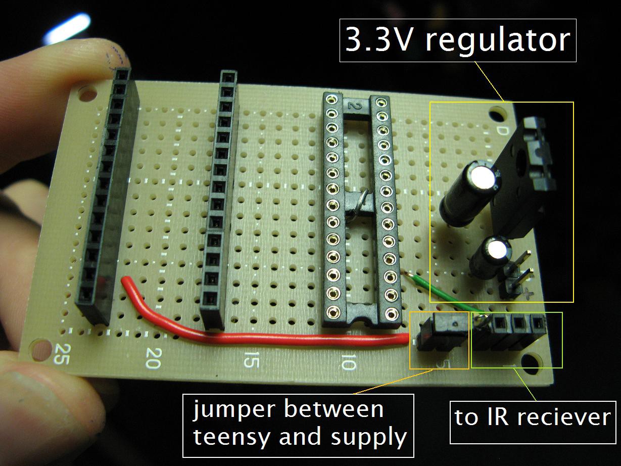
At this point:
I'm wiring things up, testing bits of code and hardware, and making it look nice.
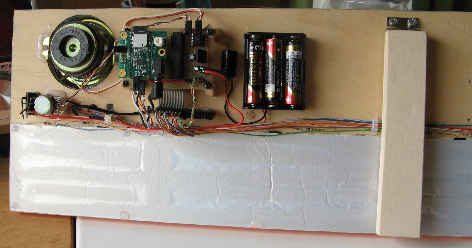


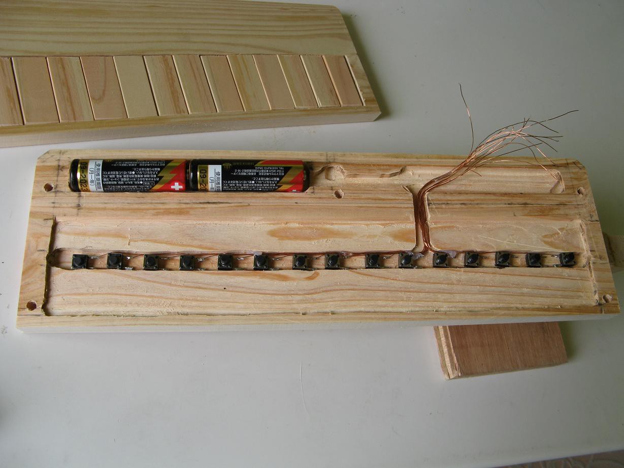
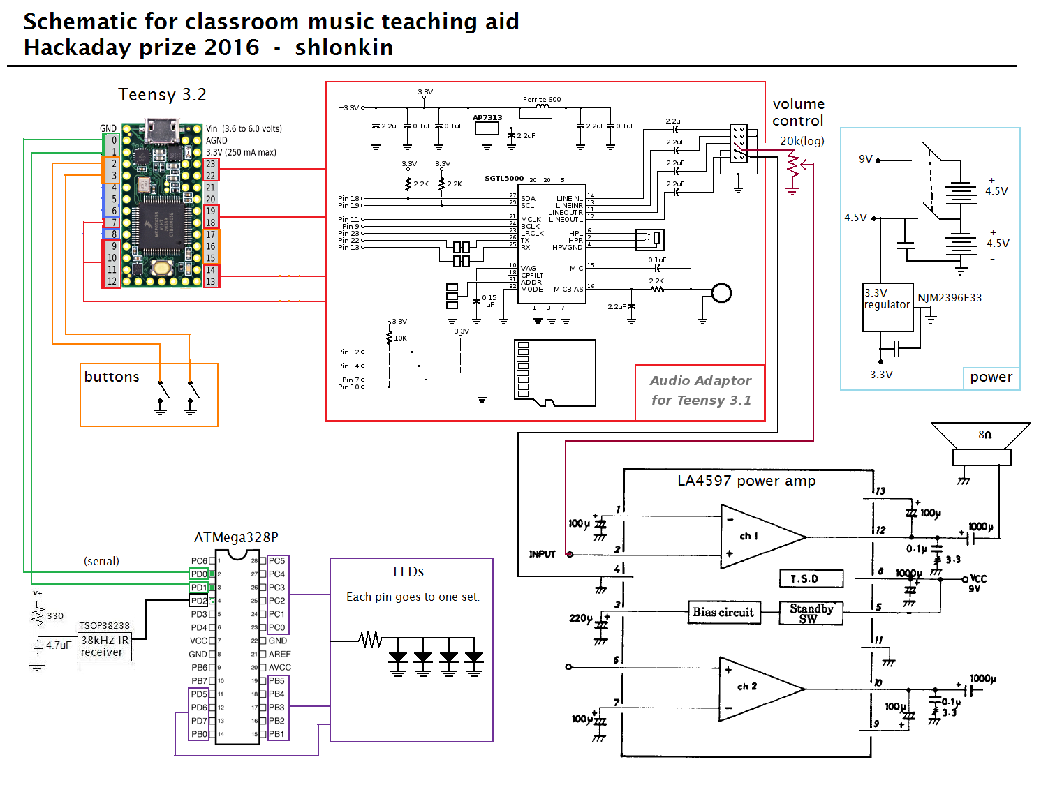
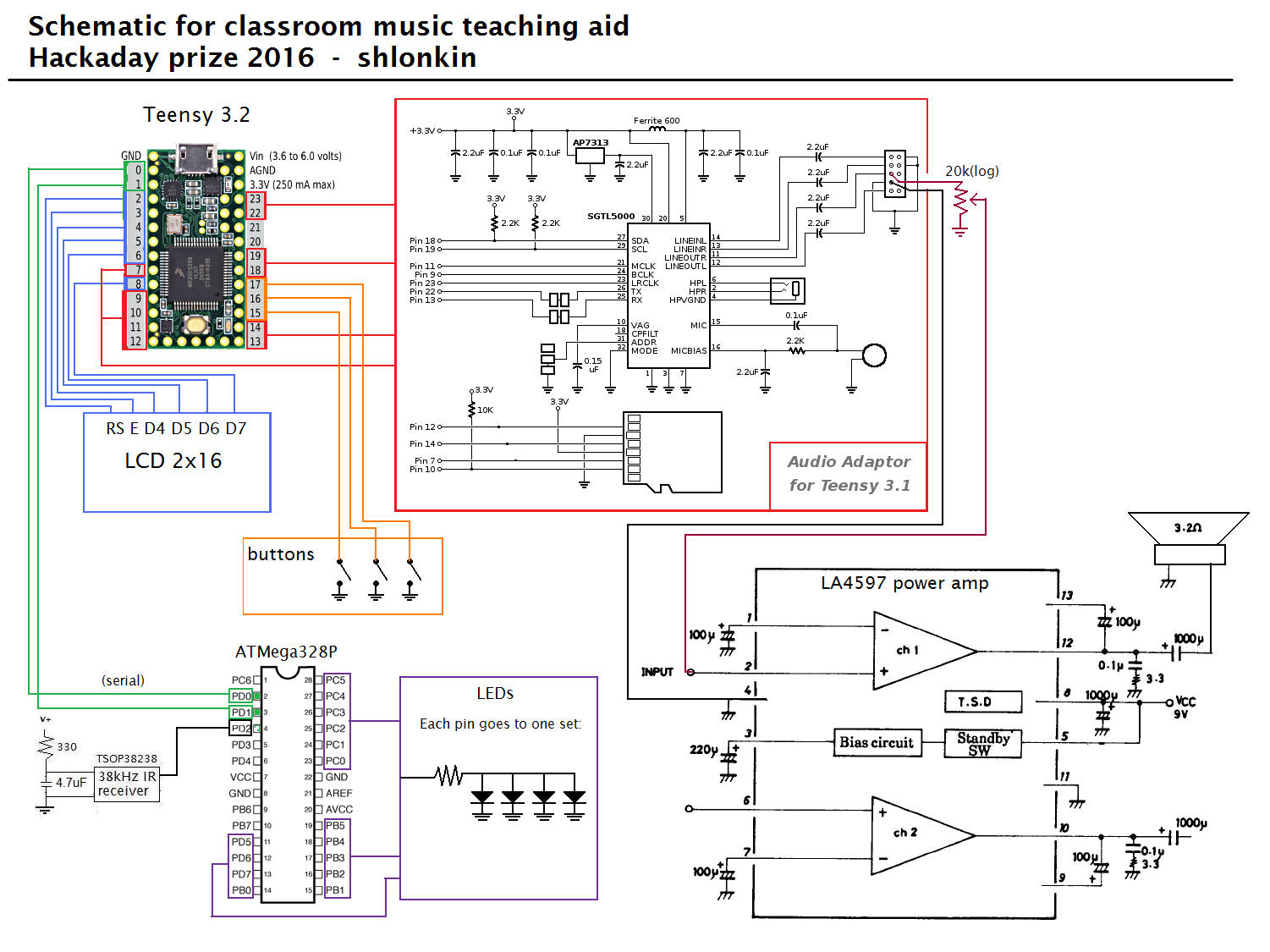
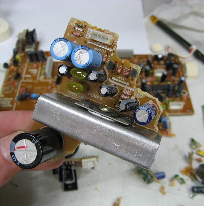
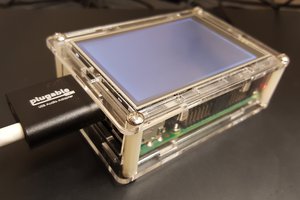
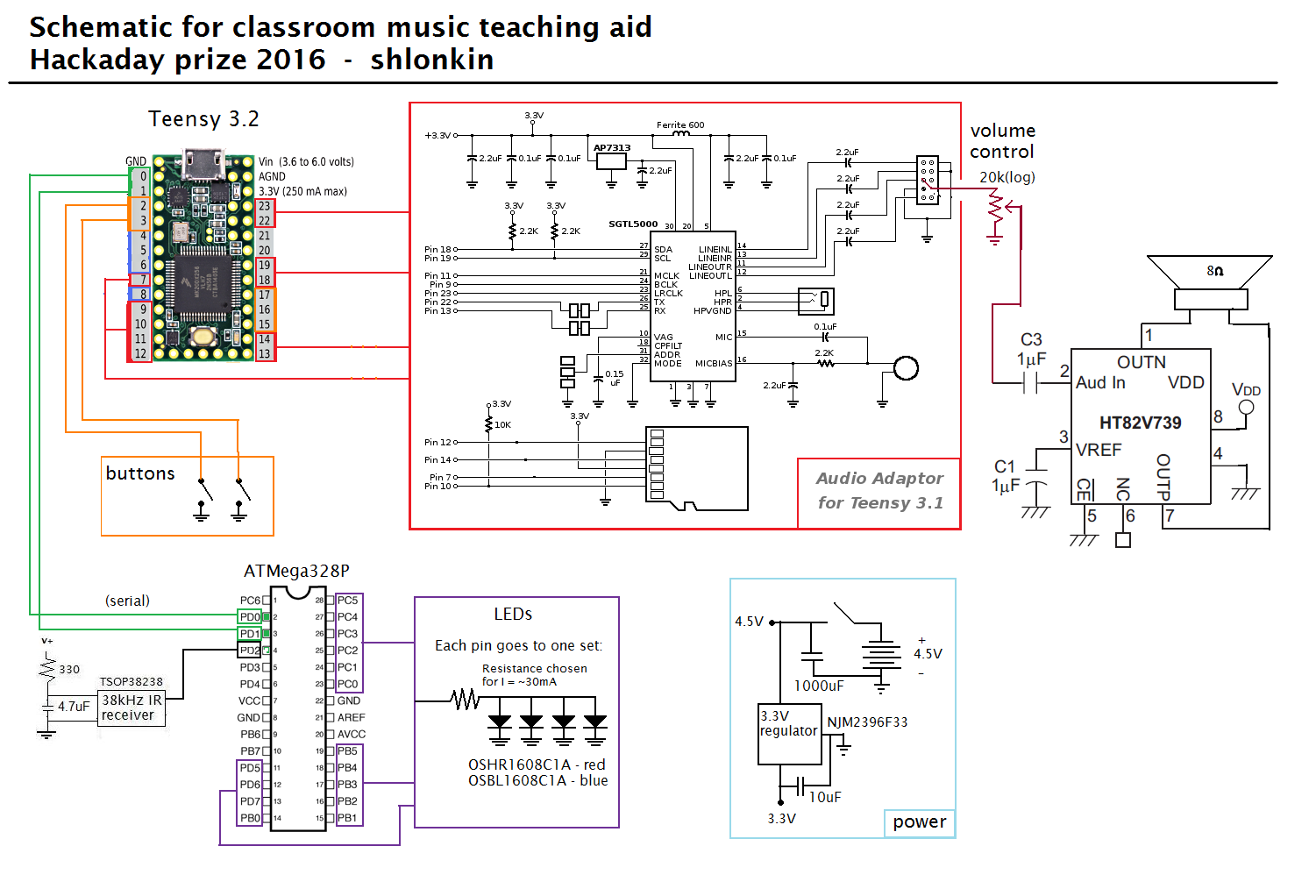 The main difference is the HT82V739 audio power amp on the right which replaces that big chunk of circuitry I had before. One other change is the removal of the second battery pack since this amp is designed for low voltage, battery powered devices.
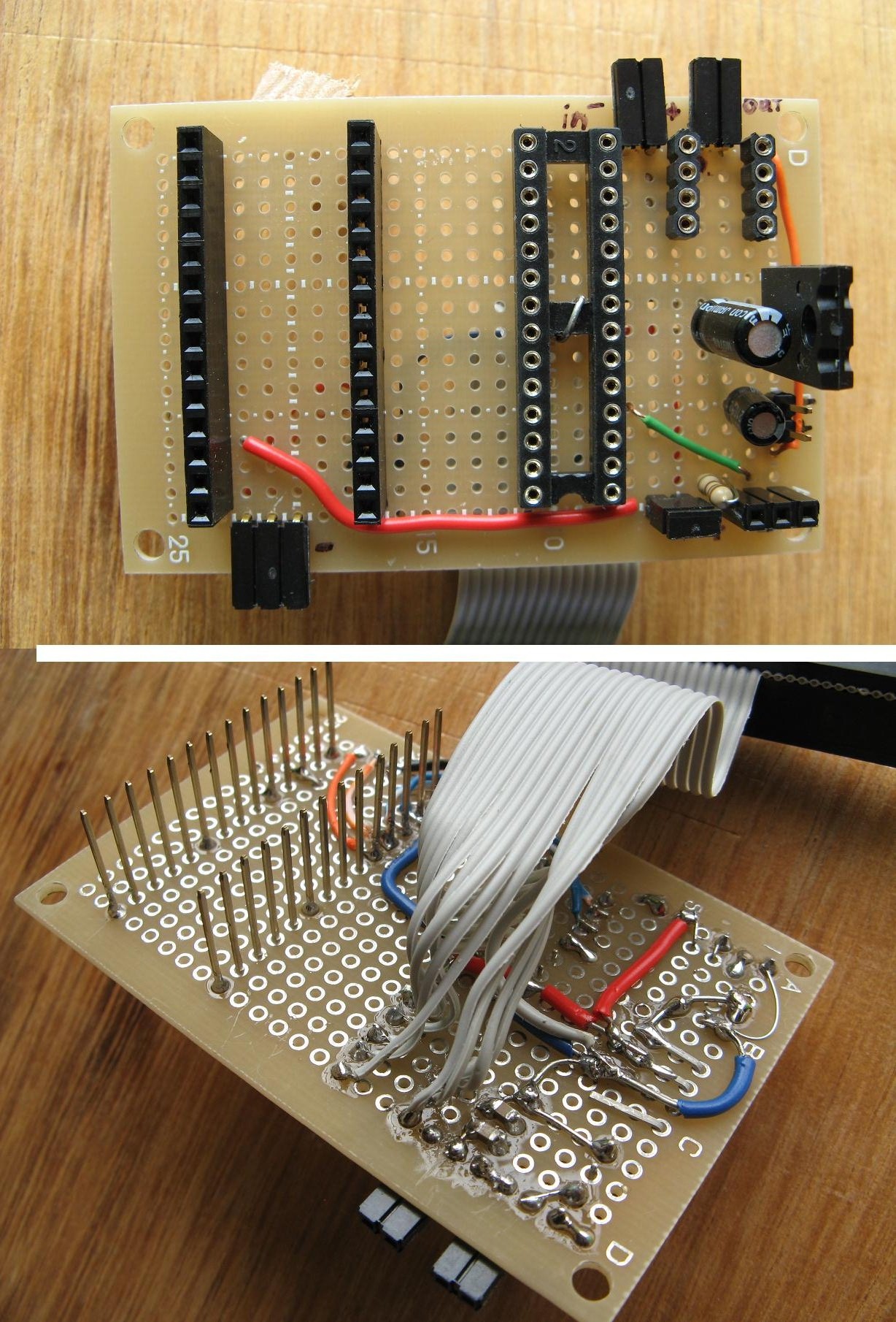
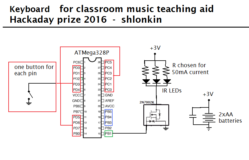
 And here's an updated basic diagram
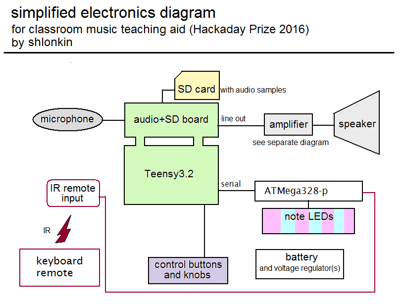
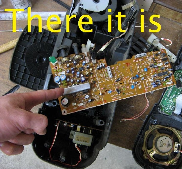
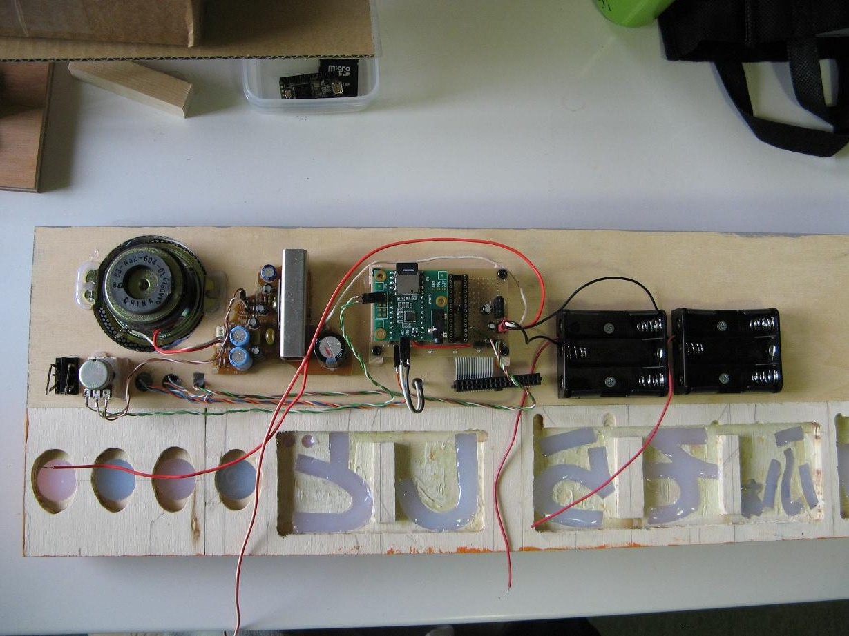
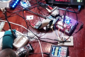
 Just to make sure this would work I rigged everything up and plugged it into the headphone jack on my computer. Everything worked well. This is encouraging.
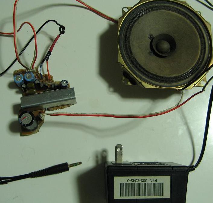
 Now I'll tell you how I got there. Here is a rough sketch of the idea.
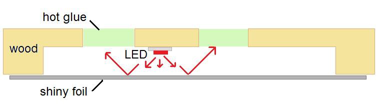
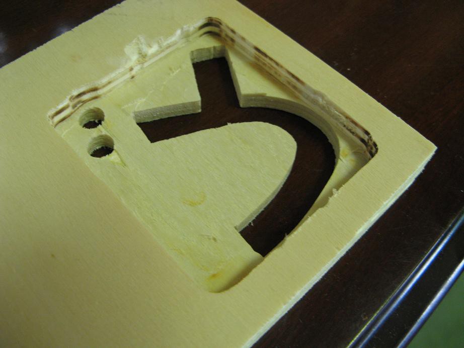
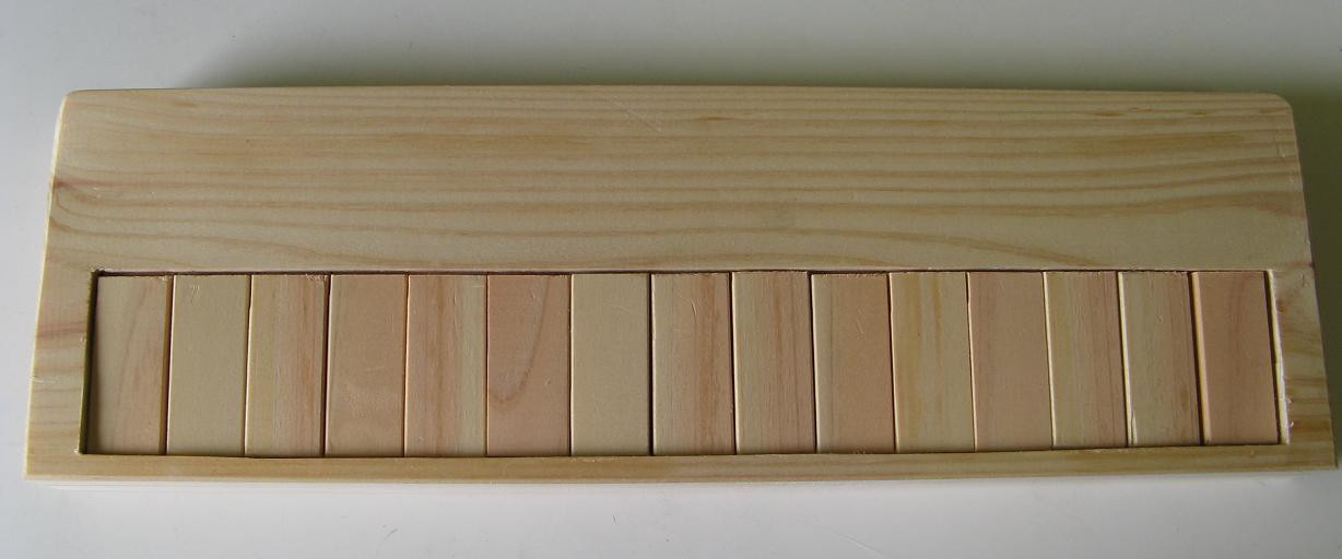
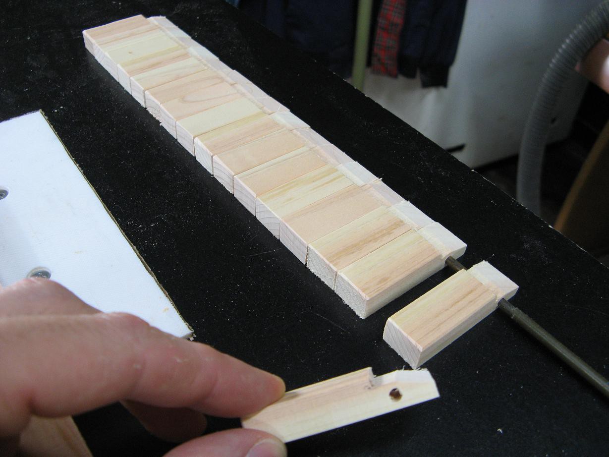
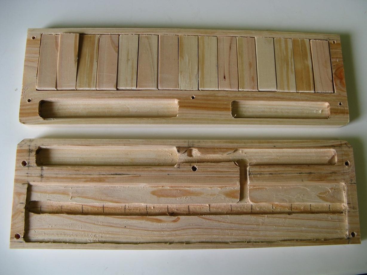
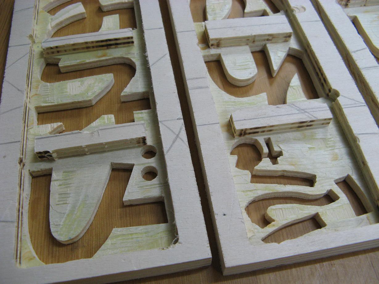
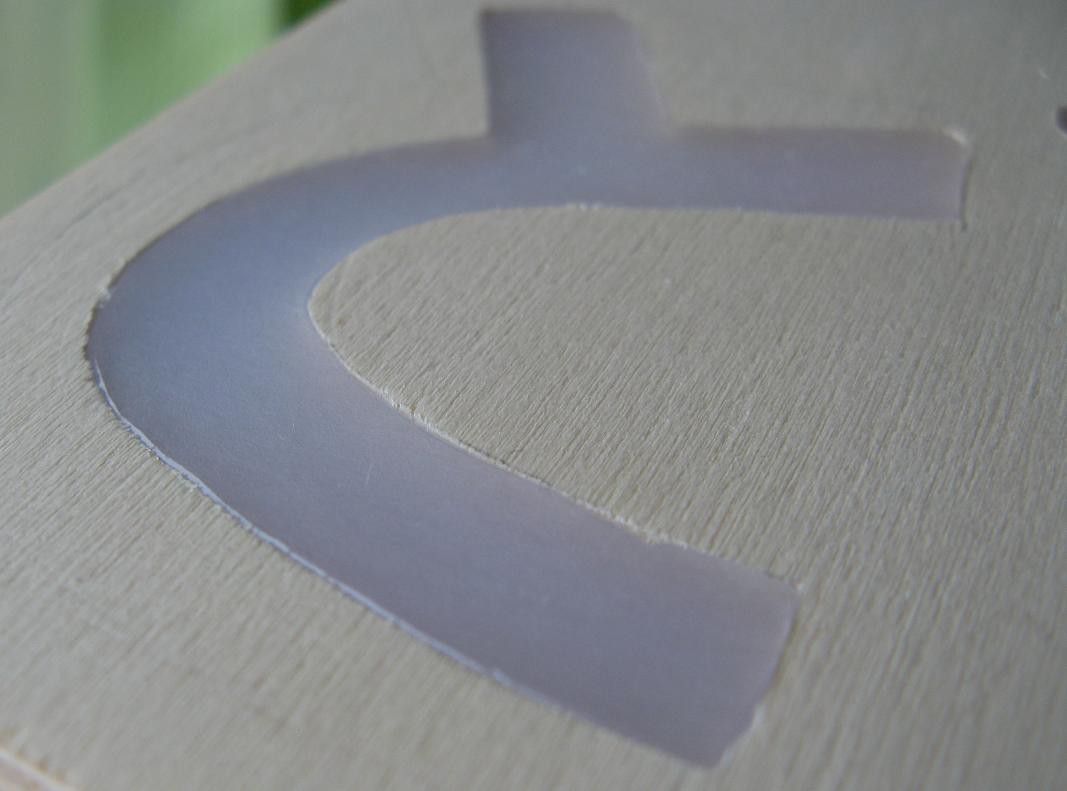
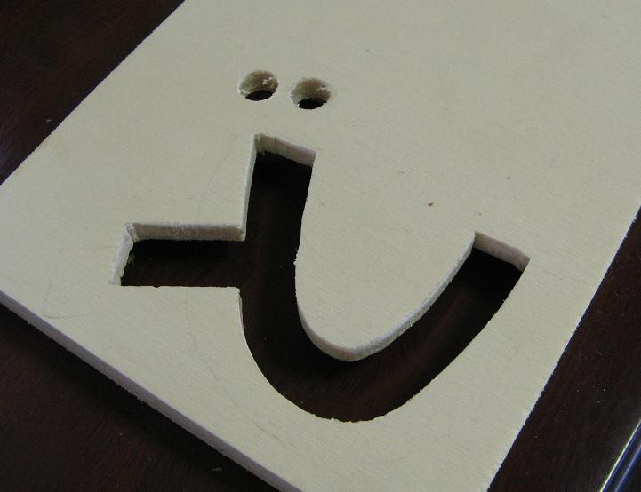 I'm using nice poplar plywood that is sooo nice to cut. Anyway, then I set it face down on some silicone baking sheet and carefully, to avoid bubbles and empty corners, filled it up with hot glue.
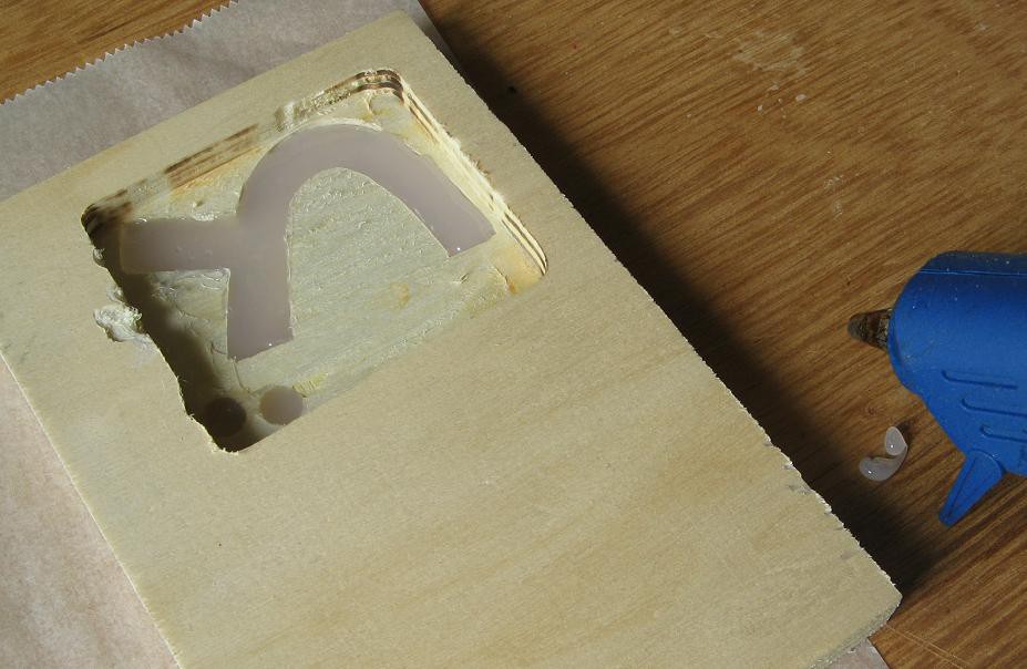 After giving it plenty of time to cool, it lifted right off the sheet and looked like this.
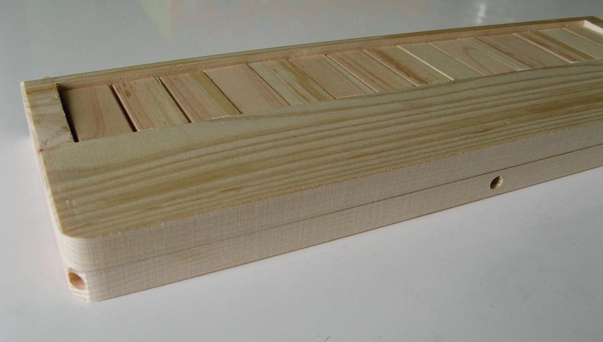
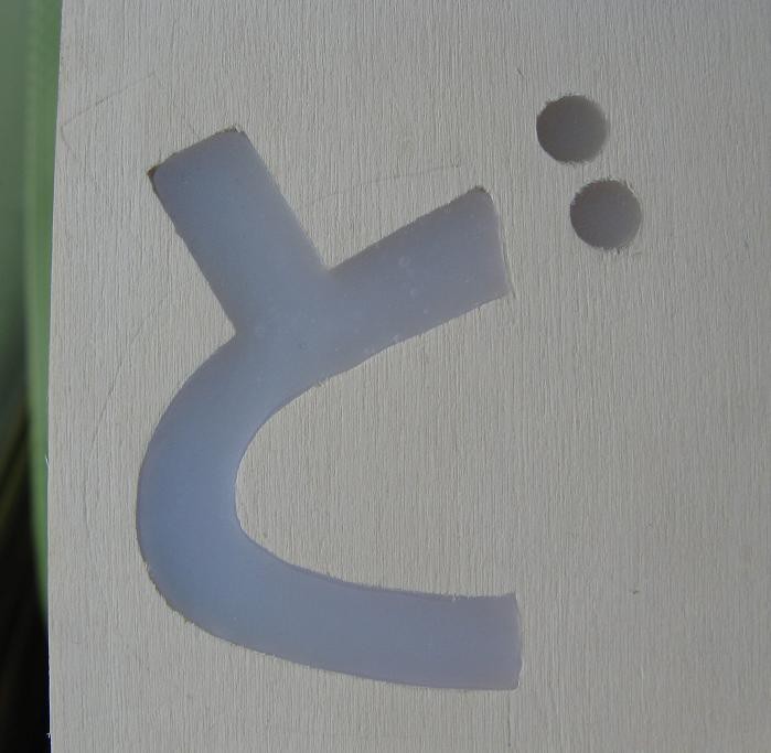
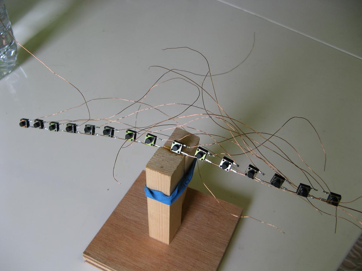
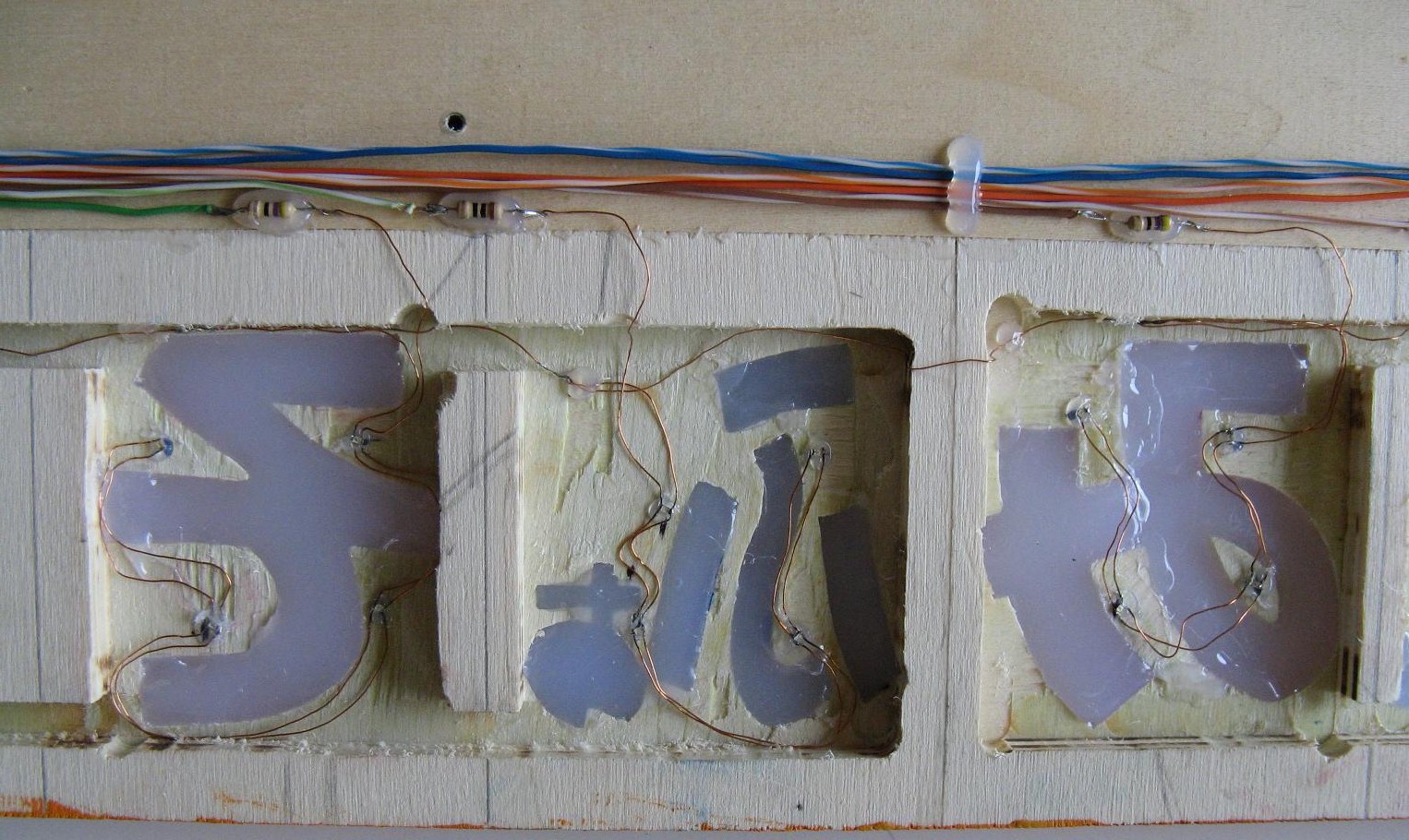
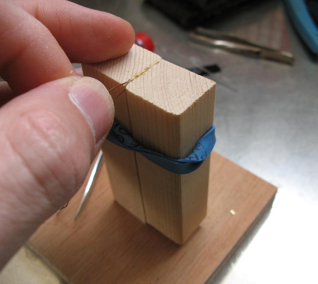
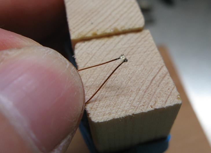
 Then it was time for the hard part. With tweezers and a way overpowered soldering iron I managed to attach four smd LEDs to some magnet wire. I somehow managed to get them all successfully connected in the right orientation on the first try. Then I tacked them on the wood with hot glue.
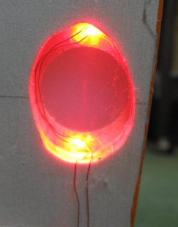
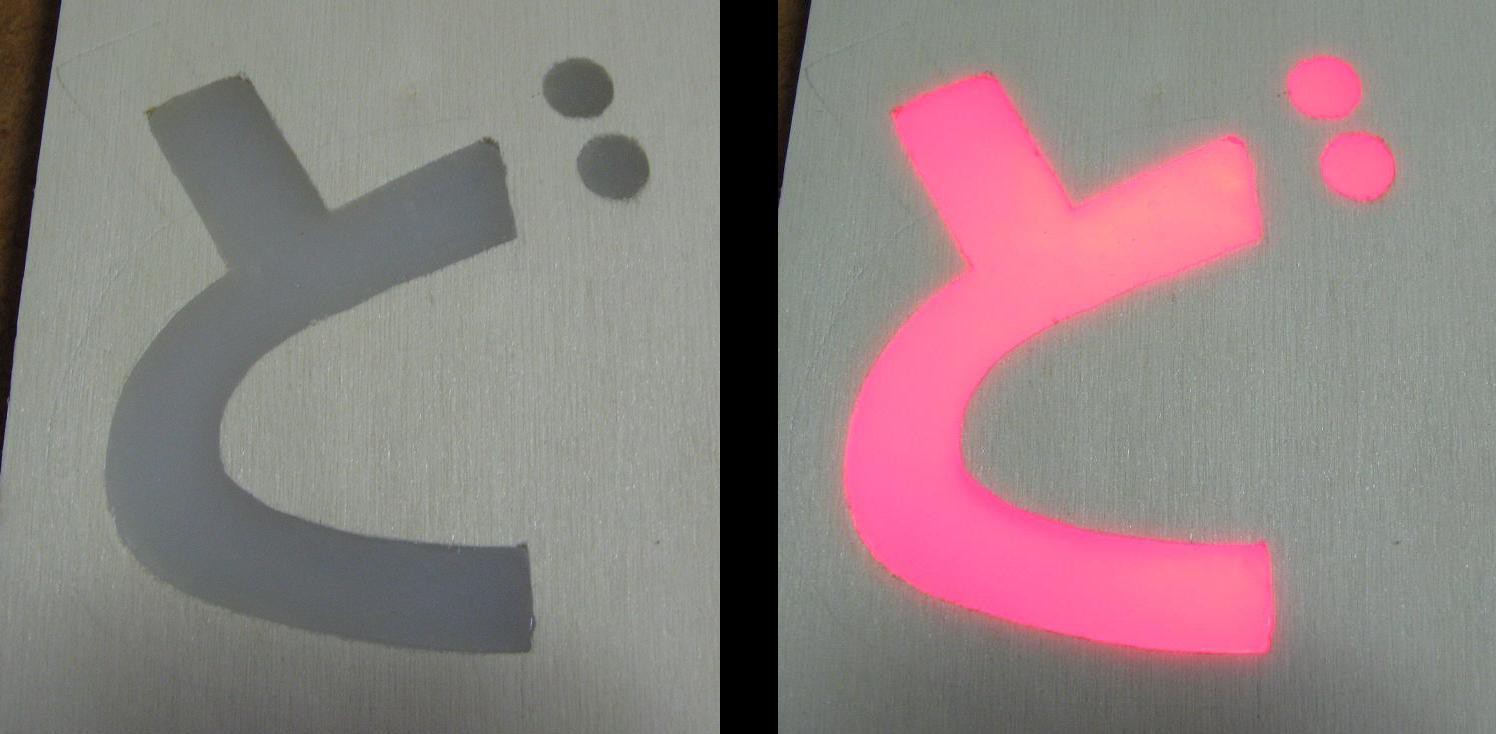
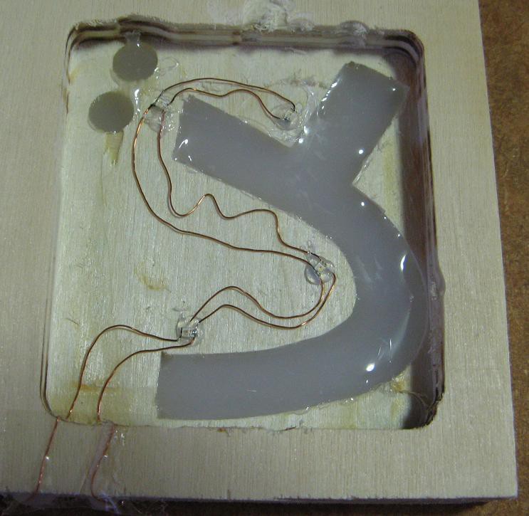 Here they are with about 50mA going through the set in parallel.
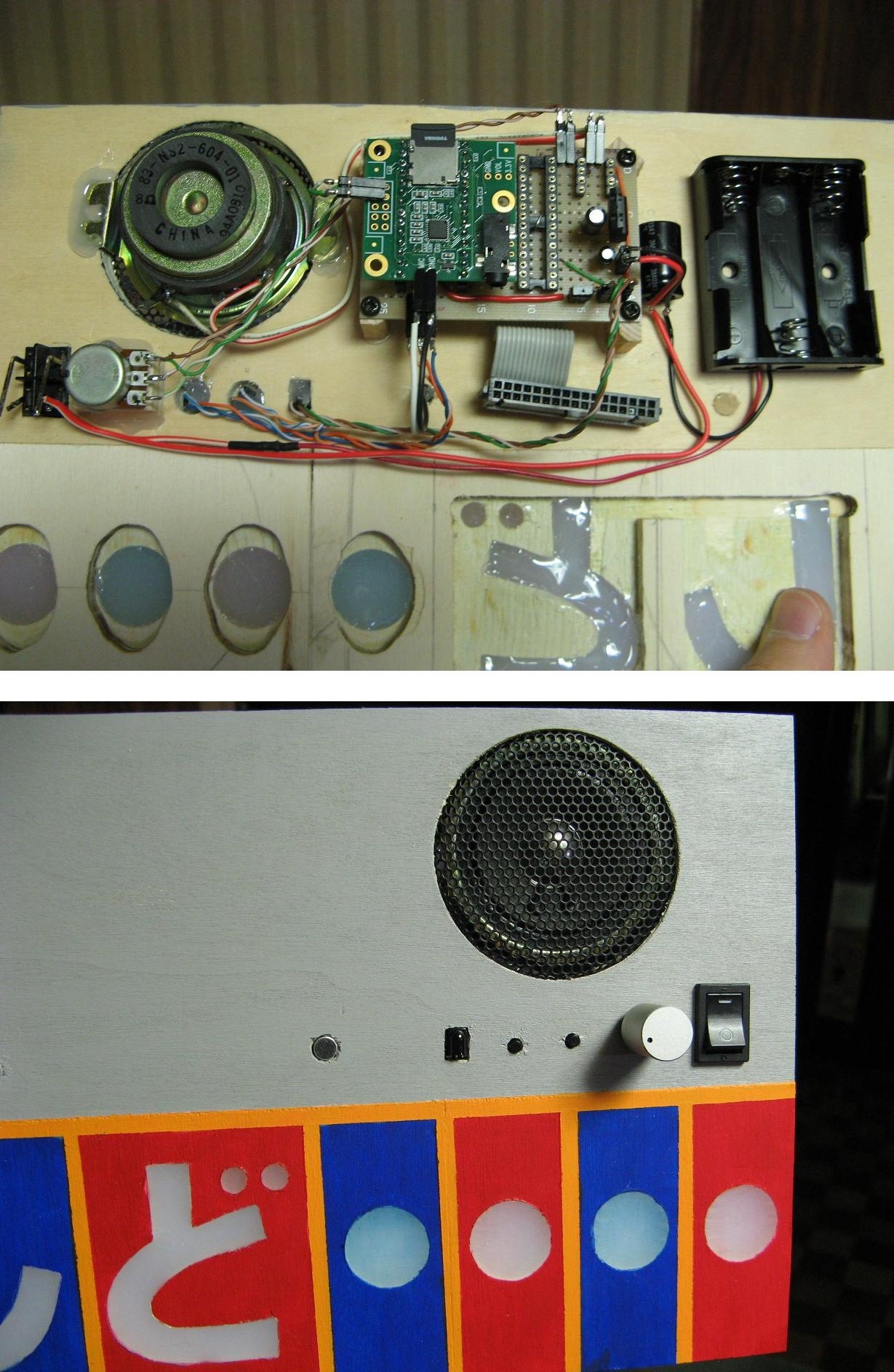
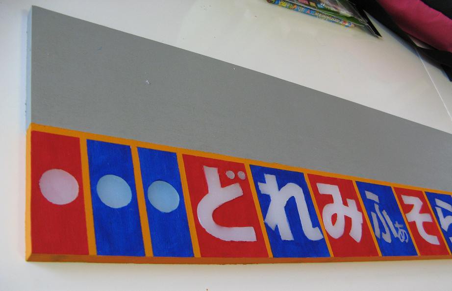
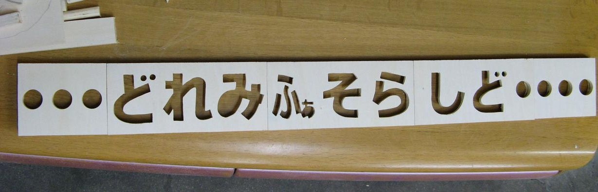
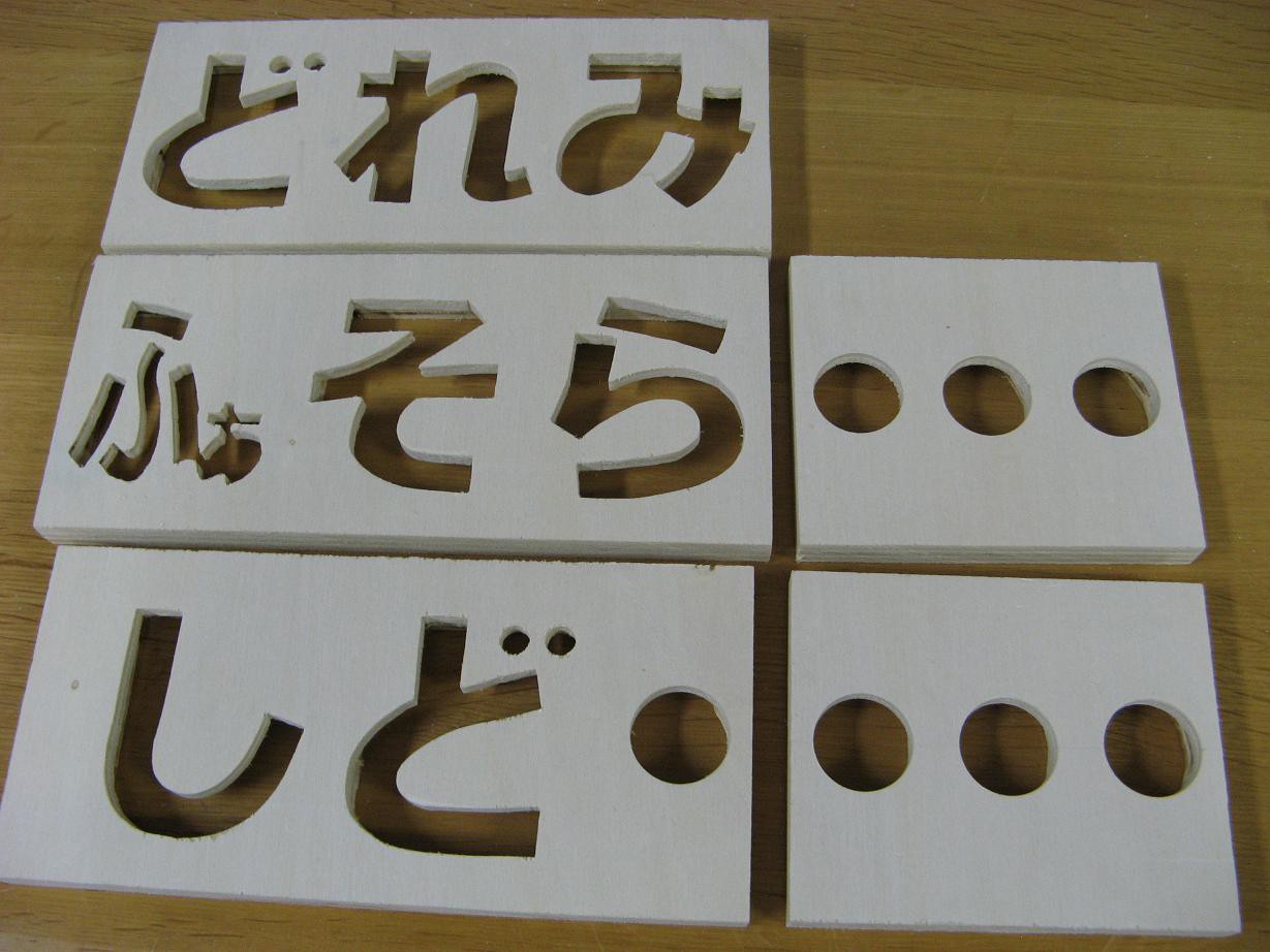
 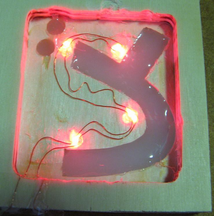 I taped some foil onto a piece of milk carton and set the device on top. The result was fantastic. I'll be using this method for the final product. But I'm not looking forward to cutting out some of the more complicated characters. I need: ど れ み ふぁ そ ら し . I think ふぁ will be a nightmare, so I might just cut the ふ part and paint the other.


 Patrick
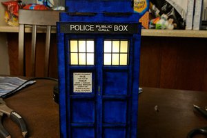
 Adam Sifounakis
 Bob Baddeley
The classroom music teaching aid is a device that can be used in the classroom to help children learn how to play an instrument, sing or dance. The device has a microphone and speakers, allowing teachers to listen to the sounds being made by their students and then play or record them back for their students to hear. I am now willing to visit
https://write-my-essay.online/write-my-term-paper/ website in order to find the suitable writer for help in my term paper.