When I finished the clock I put together a quick video describing the clock. There wasn't any video to speak of that was taken during construction though there were a bunch of pictures. This details section walks through many of the steps that were taken in building the clock. The video does have a time lapse of it's operation at the end.
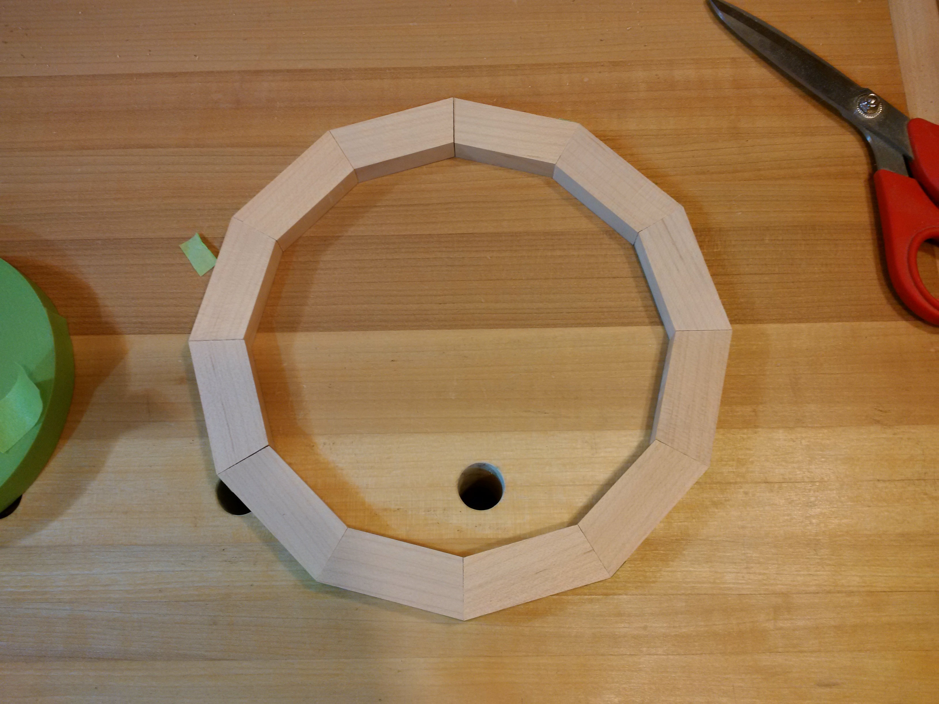
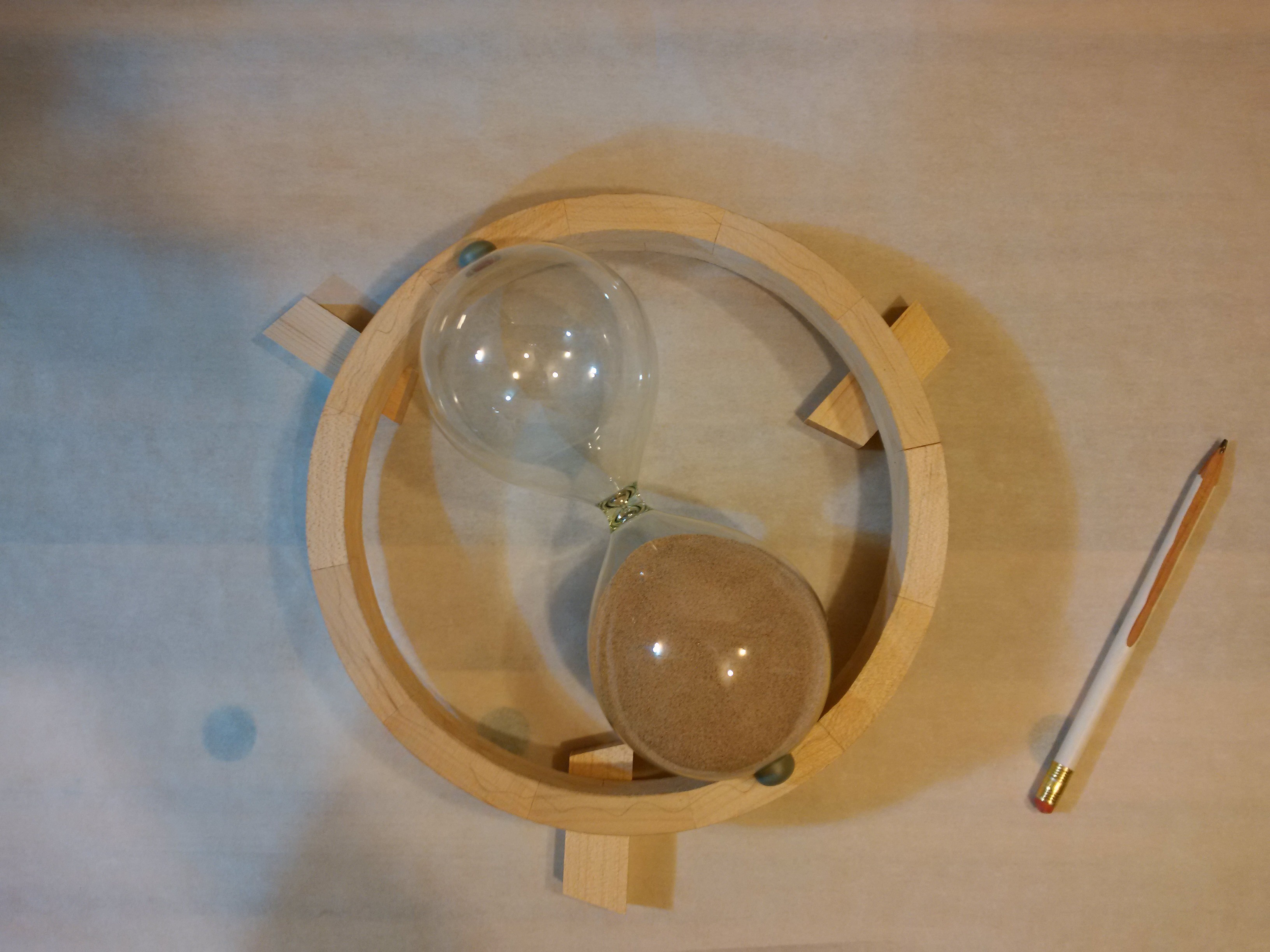
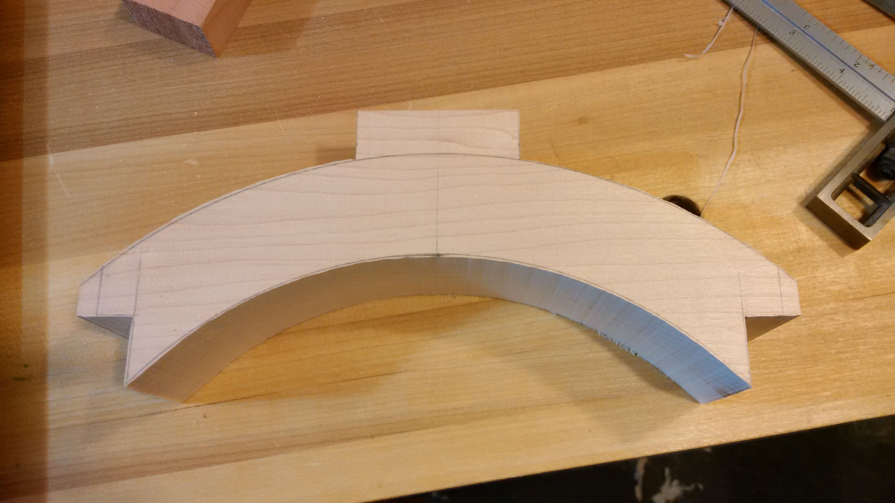
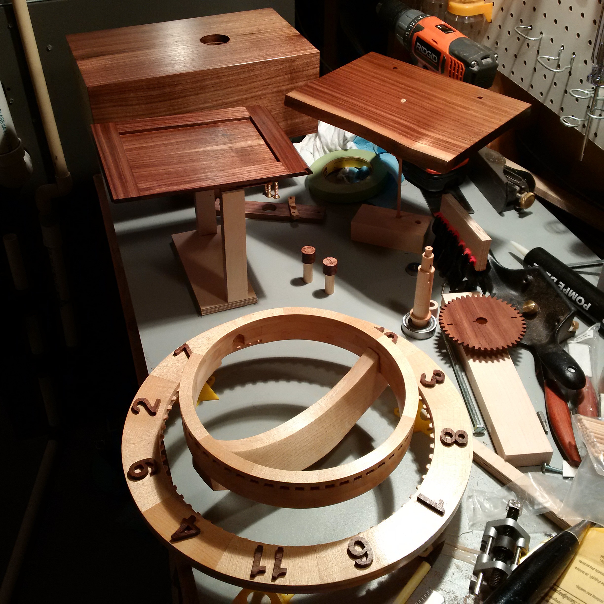
First up in making this clock work was to decide how to flip the hourglass. I figured that having the inner ring held by a curved piece going across where the hourglass is thinnest would give me a nice spot to attach an axle of some sort. That approach meant that I needed the the ring to be pretty strong as it would be carrying all the weight. It also needed to be thin or the size of the clock would get pretty big. I didn't like the look of plywood here so I went with segments of maple that I formed into a few rings and rotated them so I essentially had lap joints.
This also caused for a bit of a side project to make a saw guide as I don't have a good way of making these cuts clean enough with a power tool.
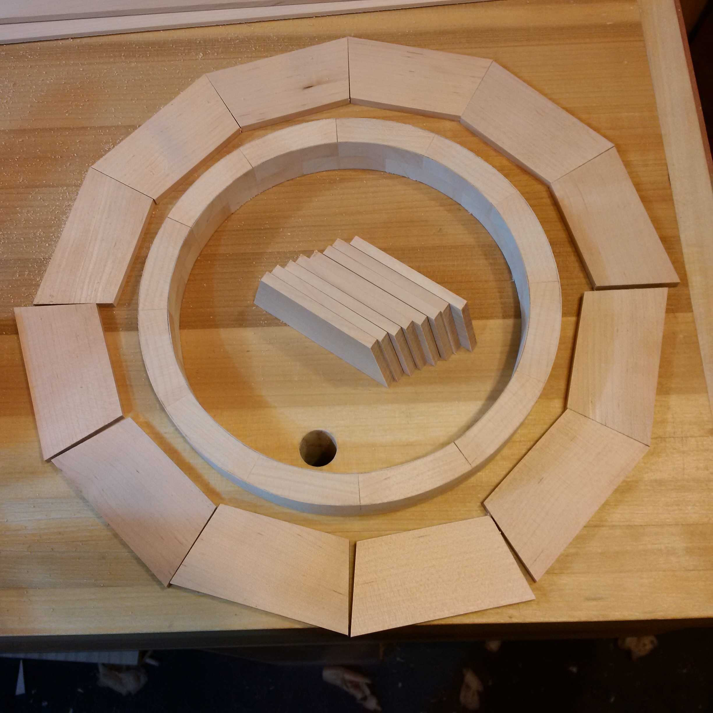
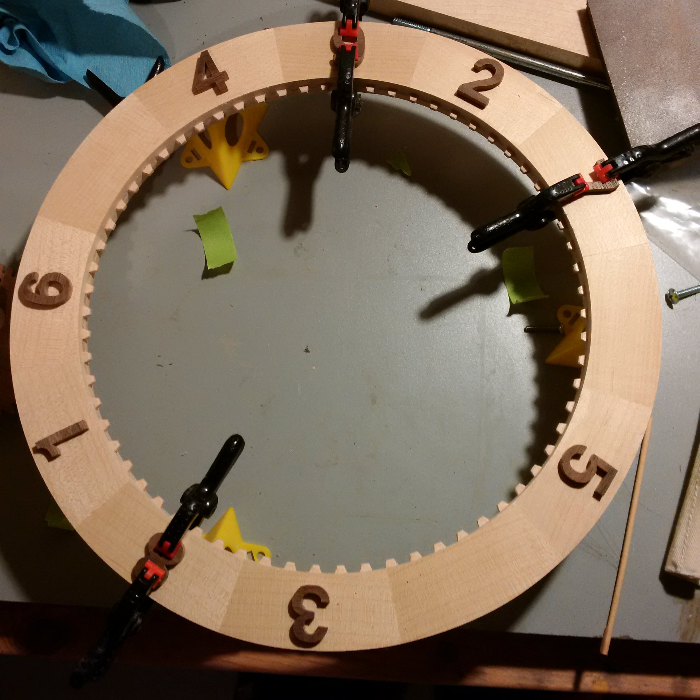
After trimming it up I was able to calculate the size of the outer ring. There are only a couple of ways that the outer ring can have a new number on the top each time. Having a large ring where the half rotation of the inner rotated the outer 30 degrees (six times the size of the inner) was not what I was looking for. Having the next number at the "5 o'clock" position makes for a nice look and keeps the ratio of the mating ring surfaces 5:6.
The outer ring is not as deep but is wide enough to put on some reasonable looking numbers.
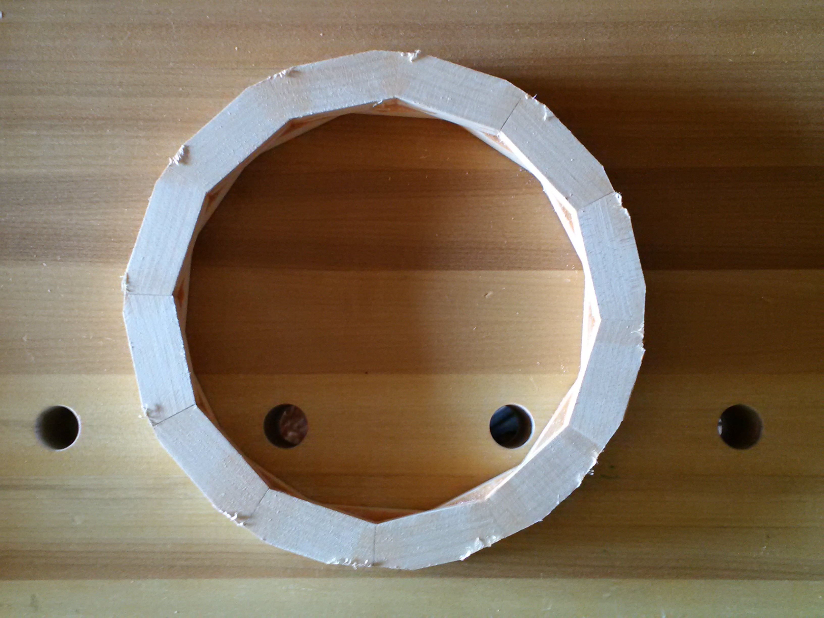
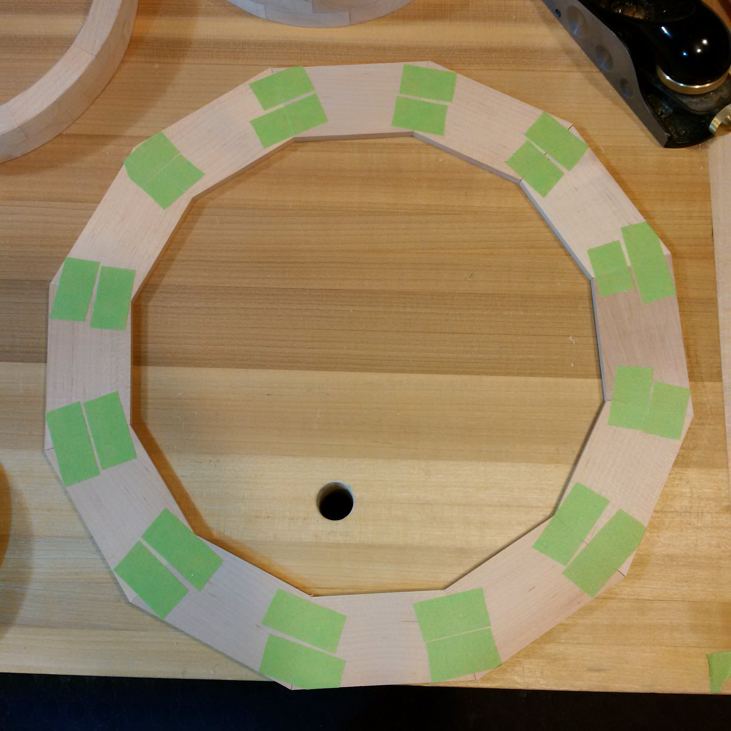
All of these rings were first glued together on their edges. To do that I taped one face together, put glue in the joints and pressed it down on the bench with a weight till it was set.
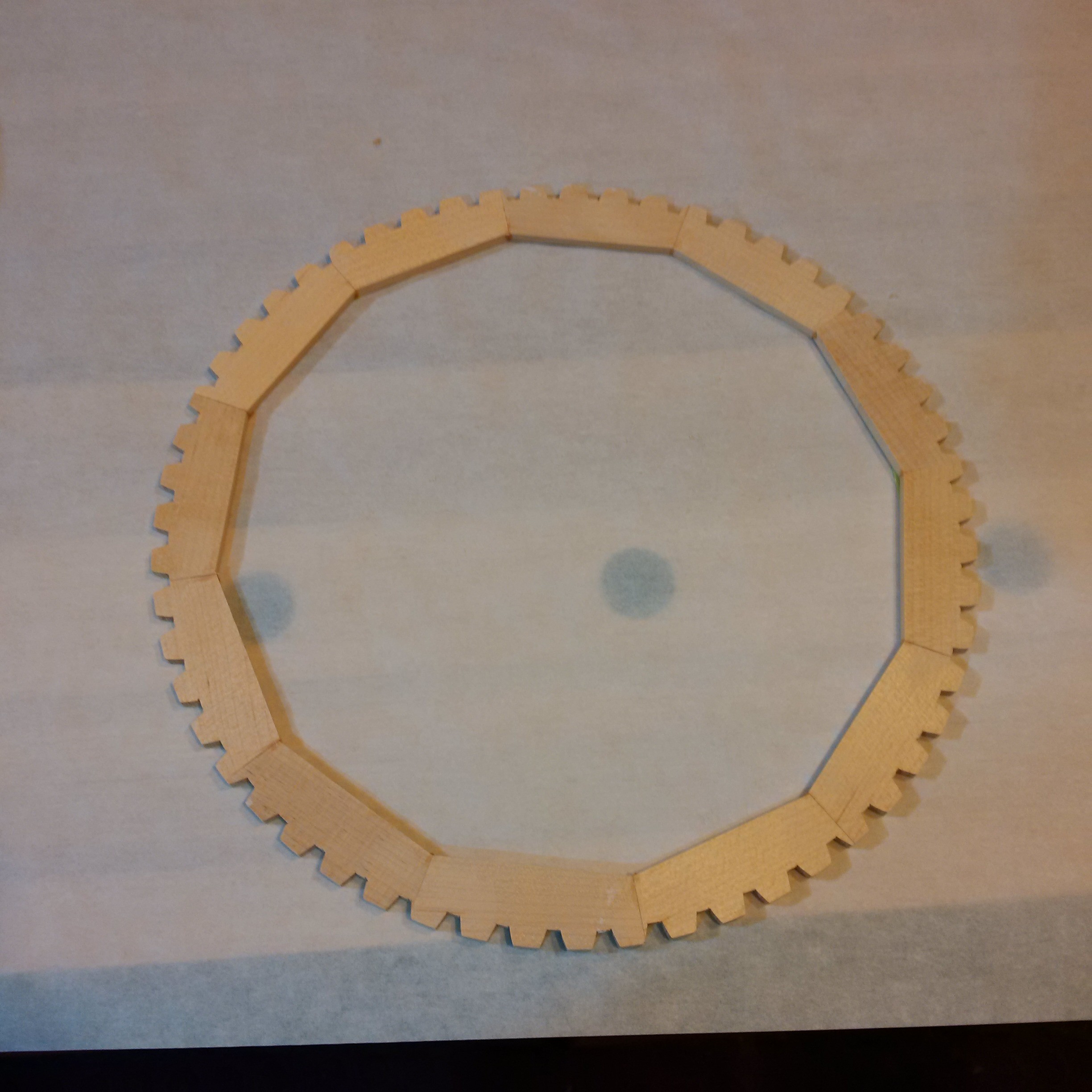
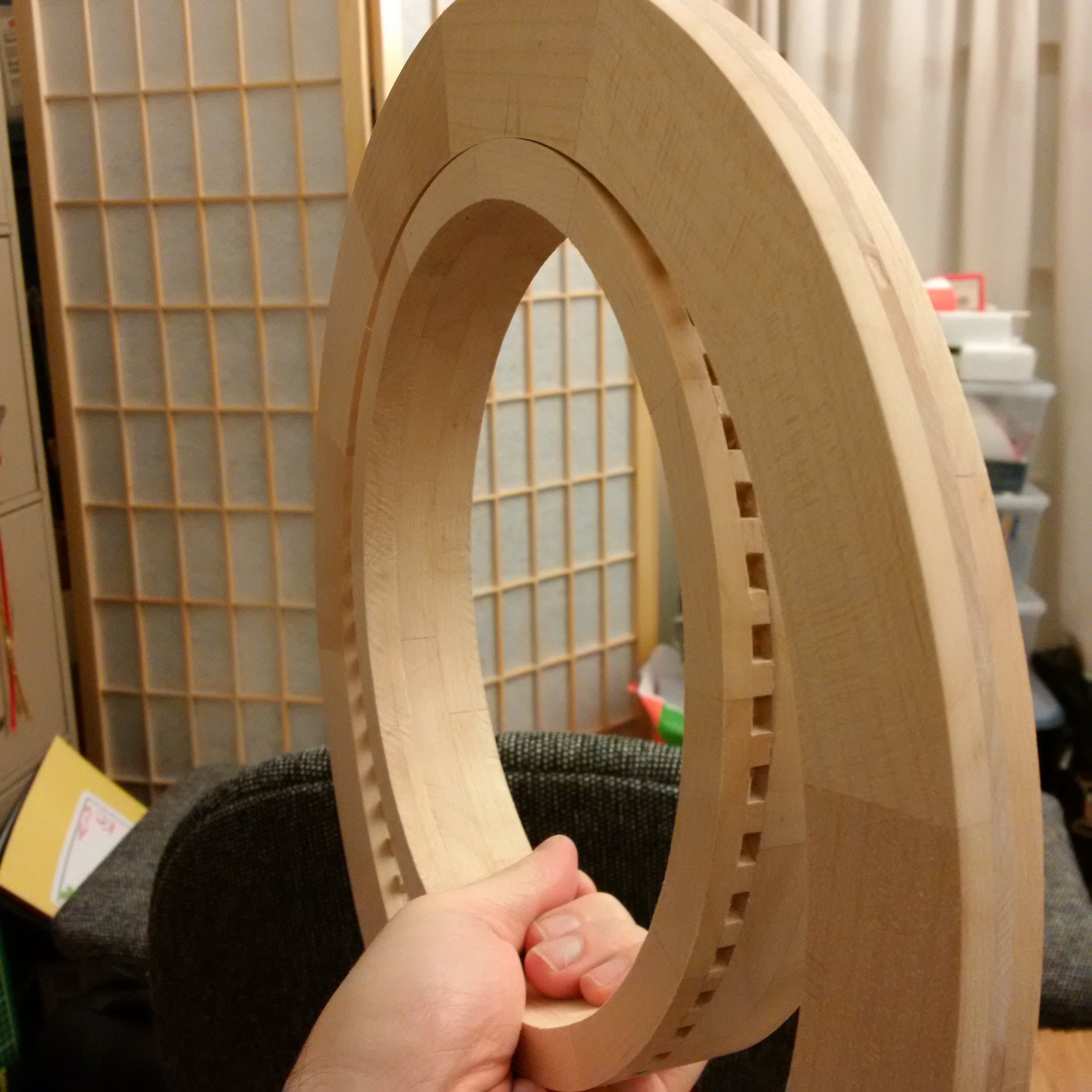
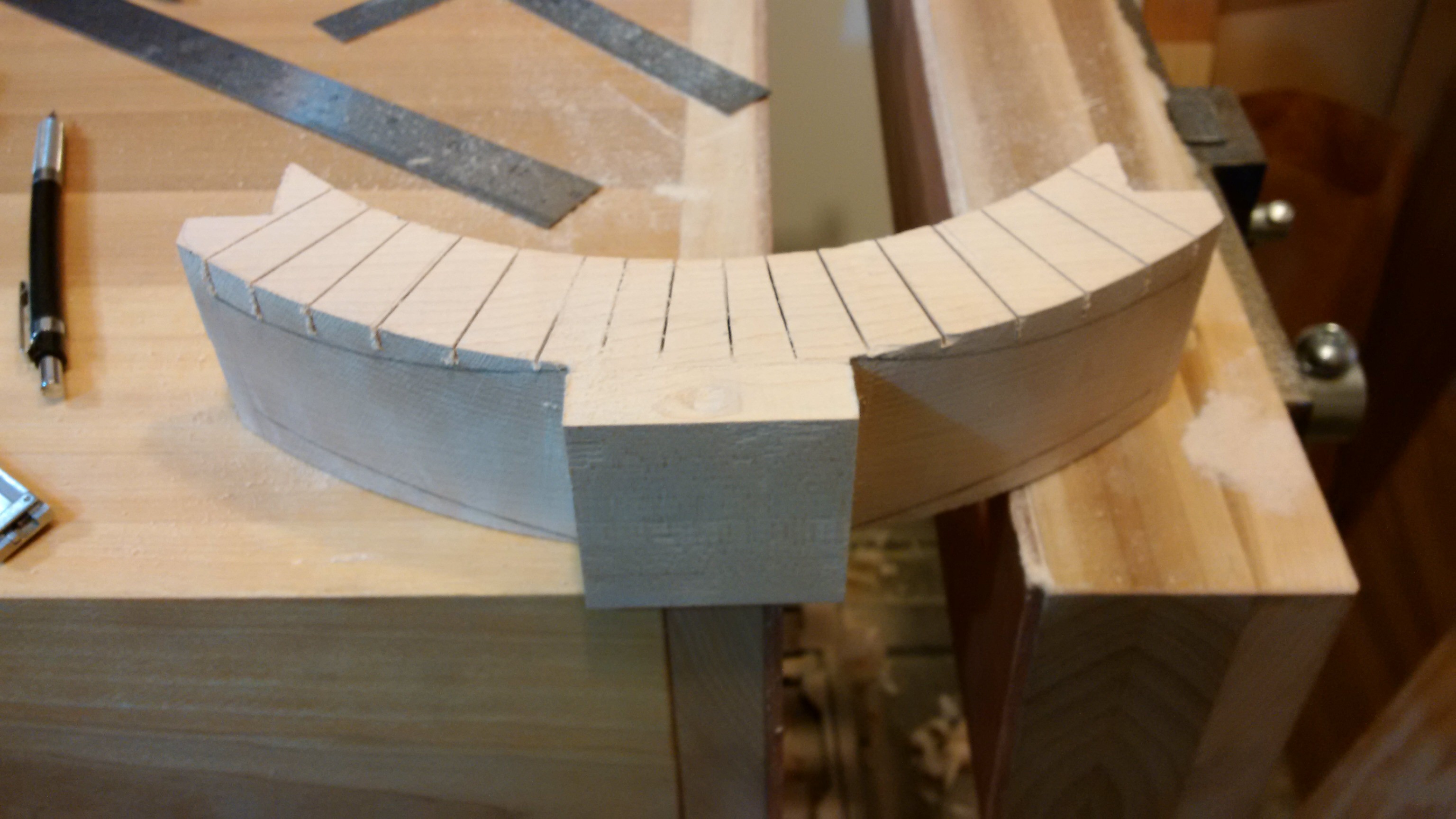
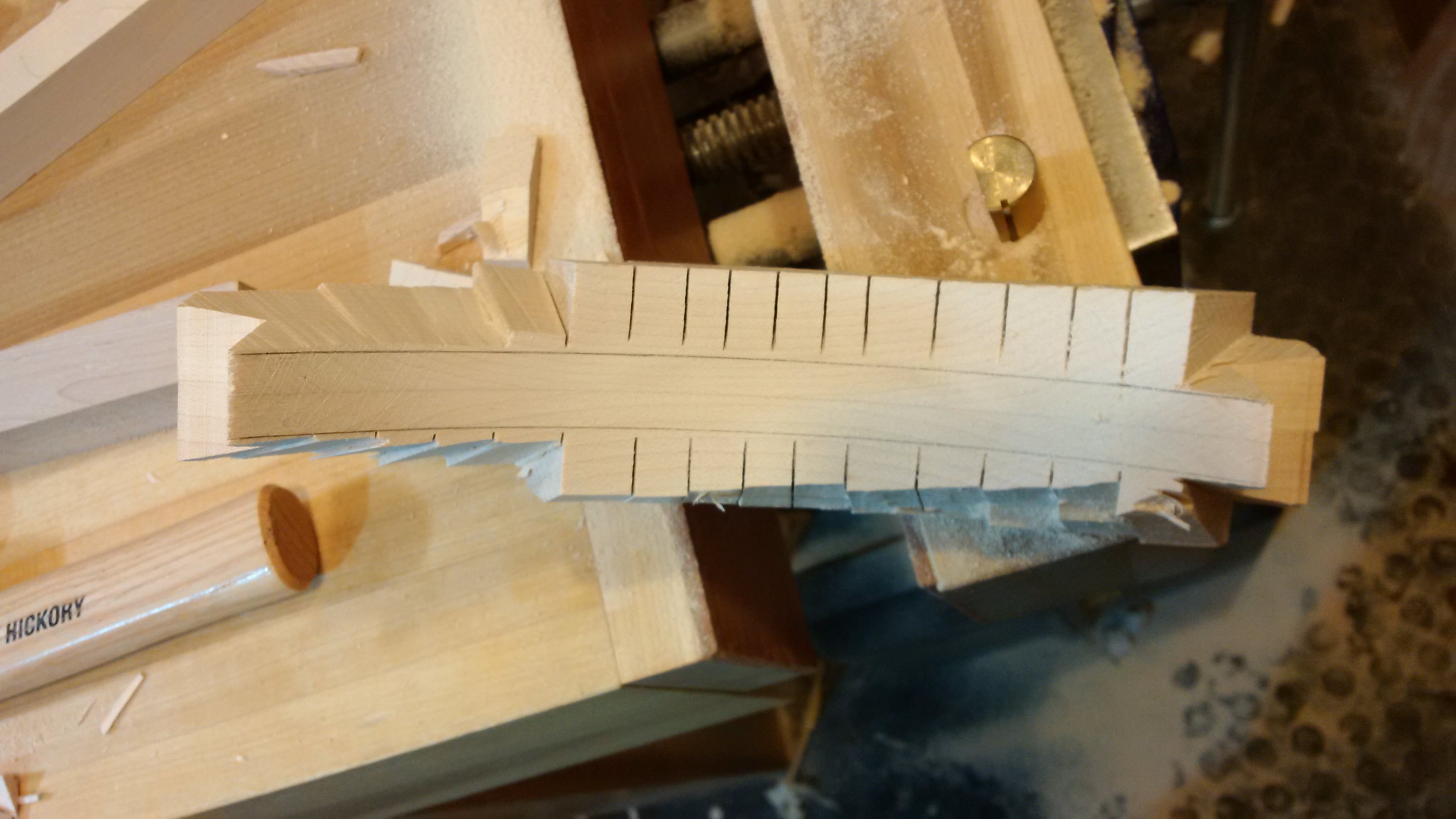
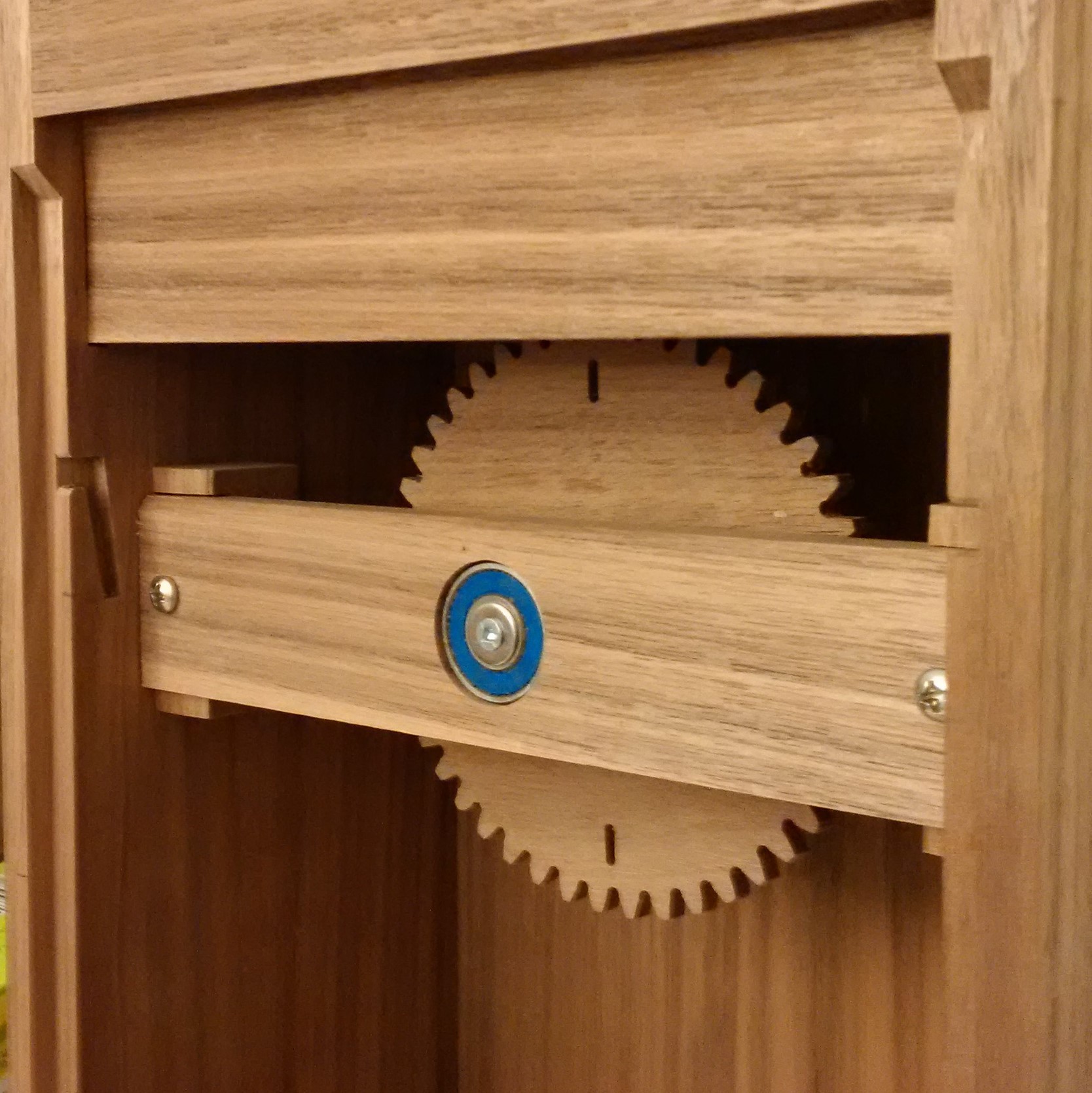
Next up were two more problems that needed solving; keeping the outer ring in sync with the inner and keeping the ring from falling off. Both were solved by having some gear teeth built into the rings. I chose to only have the teeth protrude from the outer ring as I liked the look better and it made things slightly simpler. I switched the grain direction for the outer teeth so they would not break off.

I glued them together like the other layers, glued on a template and cut them out on the scroll saw. A saner person could have chosen fewer teeth however I realized that by using 55 and 66 teeth I'd have the ability to make a 24 hour ring so I went with that.

Turns out that I was off on my measurement of the length of the hourglass by a few mm so I had to take some out of the middle.
Once I had the hourglass fitting nicely in the ring I marked out where I wanted the pockets for the top and bottom. For one end I wanted a little bracket that I could screw so that the hourglass could be removed for cleaning and for when the finish is applied.
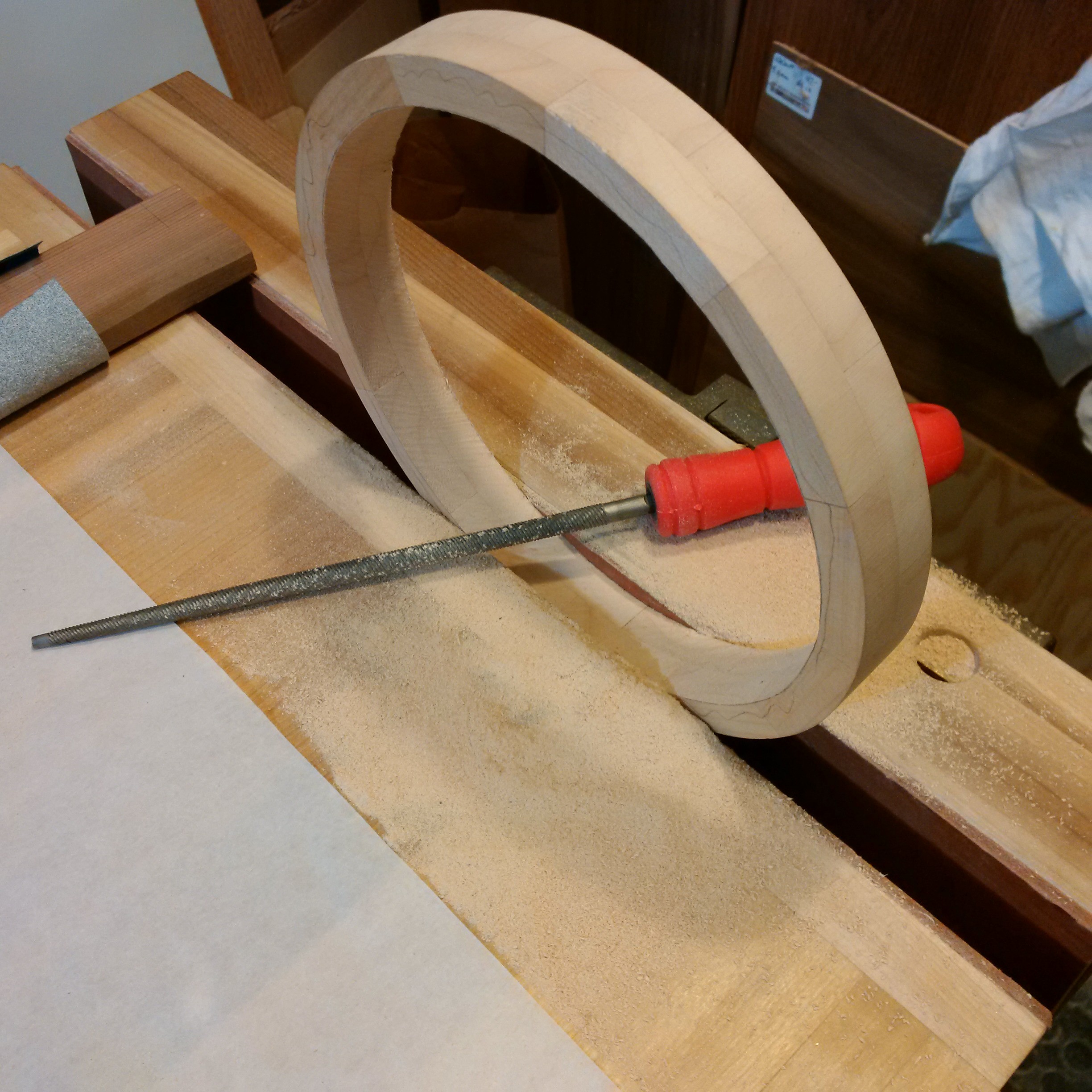
Gluing the remaining gear layers together was straightforward but took a lot of sanding, fiddling and smoothing to get everything meshing right. A lot. If I were doing this again I would take the time to make some sort of circle jig on the router to make it perfectly round.

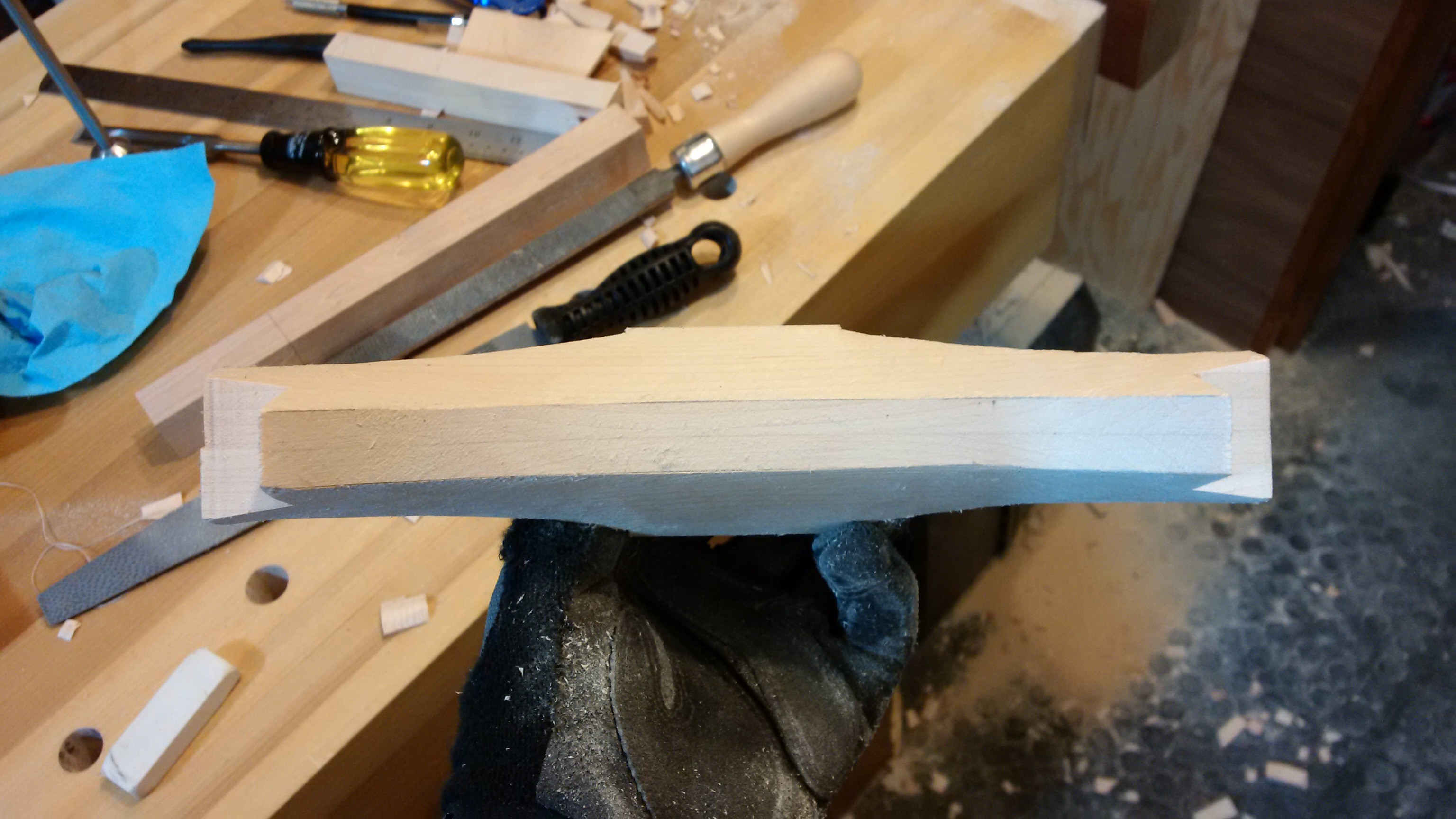
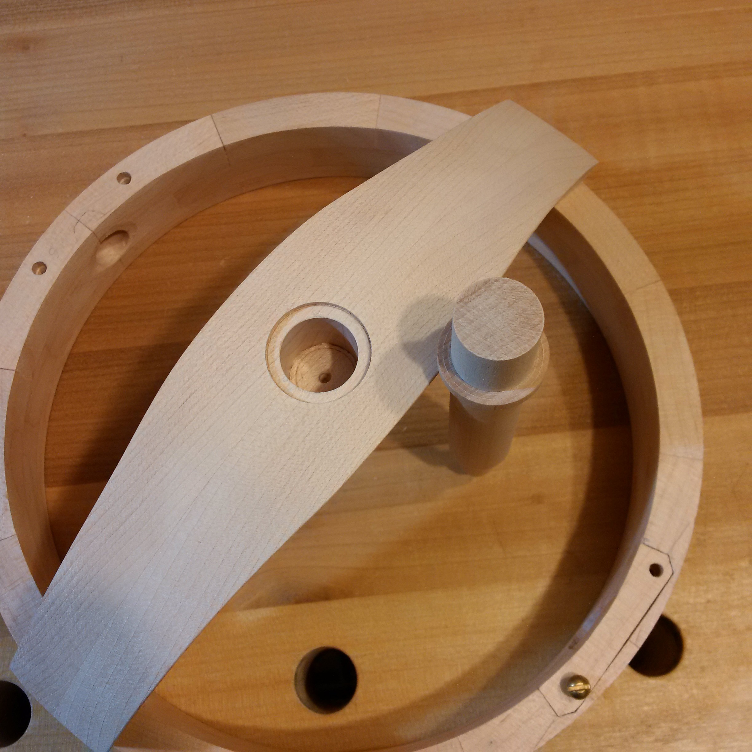
Next up was the support to connect the ring to the shaft. From the top I wanted the shape to be circular but I also like subtle curves so I tapered the support out to the sides. It was roughed out on the band saw then I added relief cuts to remove the bulk of the waste and finished with rasps and scrapers.
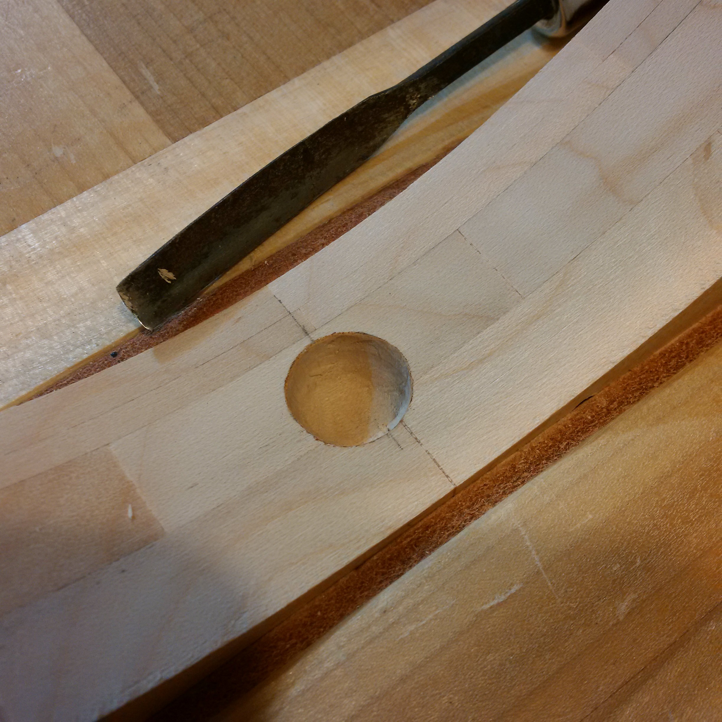
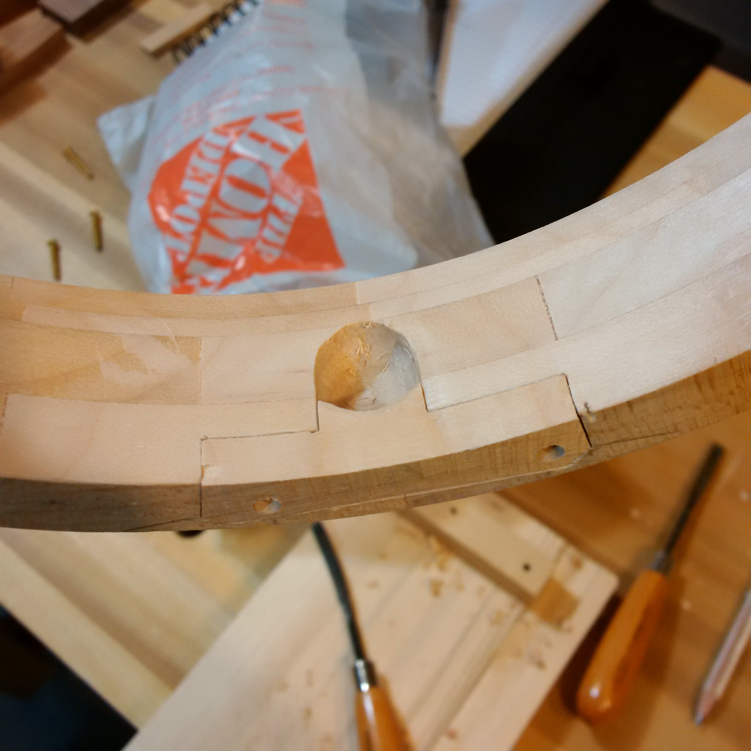
Before I went ahead and attached the brace I need to get the pockets made to hold the hourglass in. I don't have a drill that can get into that space so I went ahead and carved the pockets with a small gouge.
The other end was similar and with some fiddling I was able to make a little bracket that let the nub of the hourglass slide in.
After some more smoothing and fitting of the brace I was able to glue it in place. I found where the center of the shaft should go with a compass and drilled a mounting hole for the shaft on the drill press.
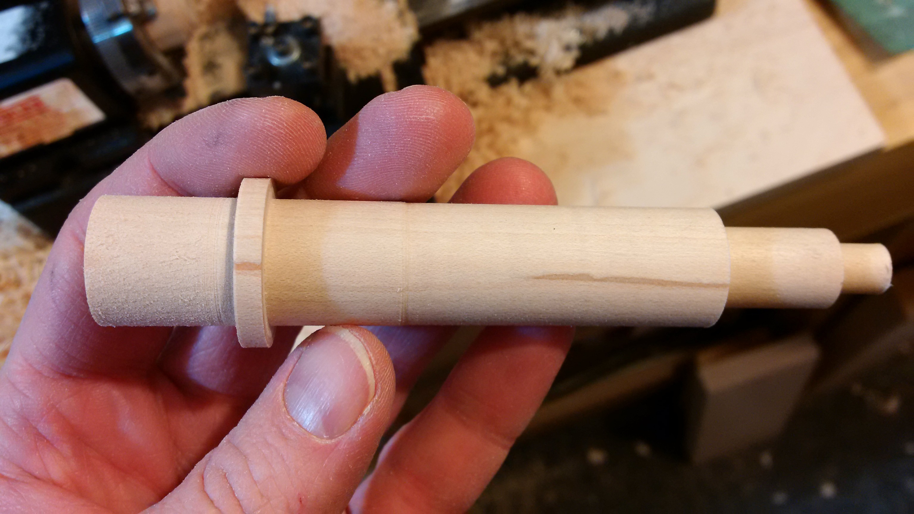
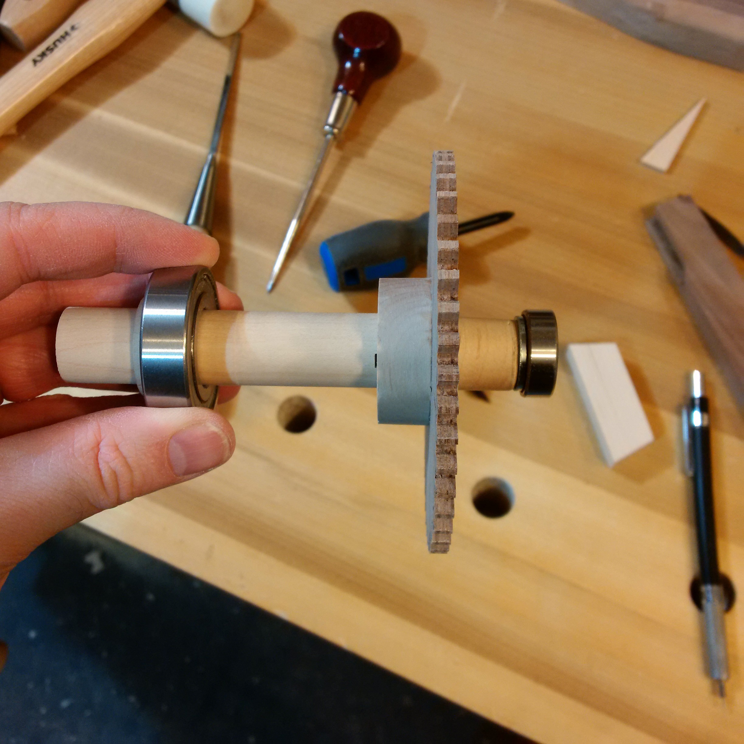
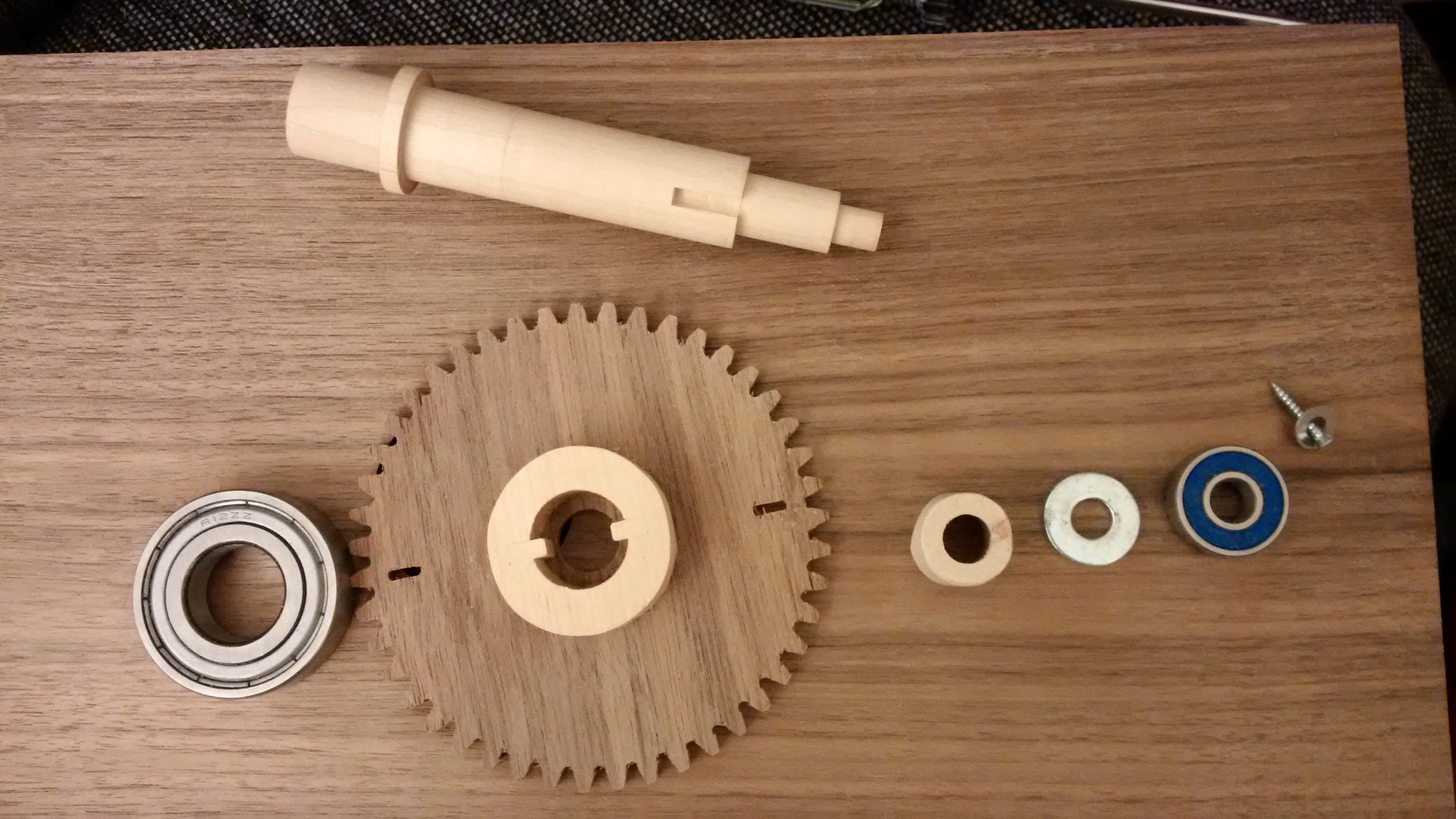
I turned the shaft on a small lathe to support the rings. It uses a 3/4" bearing at the front and a skateboard bearing at the back. I made a shoulder for a gear to register on as well.
I wanted something sturdy for that gear so I laminated four pieces of walnut veneer together to make a thin plywood. Like the maple gears I printed out the tooth pattern. The clock also needs to figure out when the hourglass is vertical so I added two slots that I could use with an optical sensor later on.
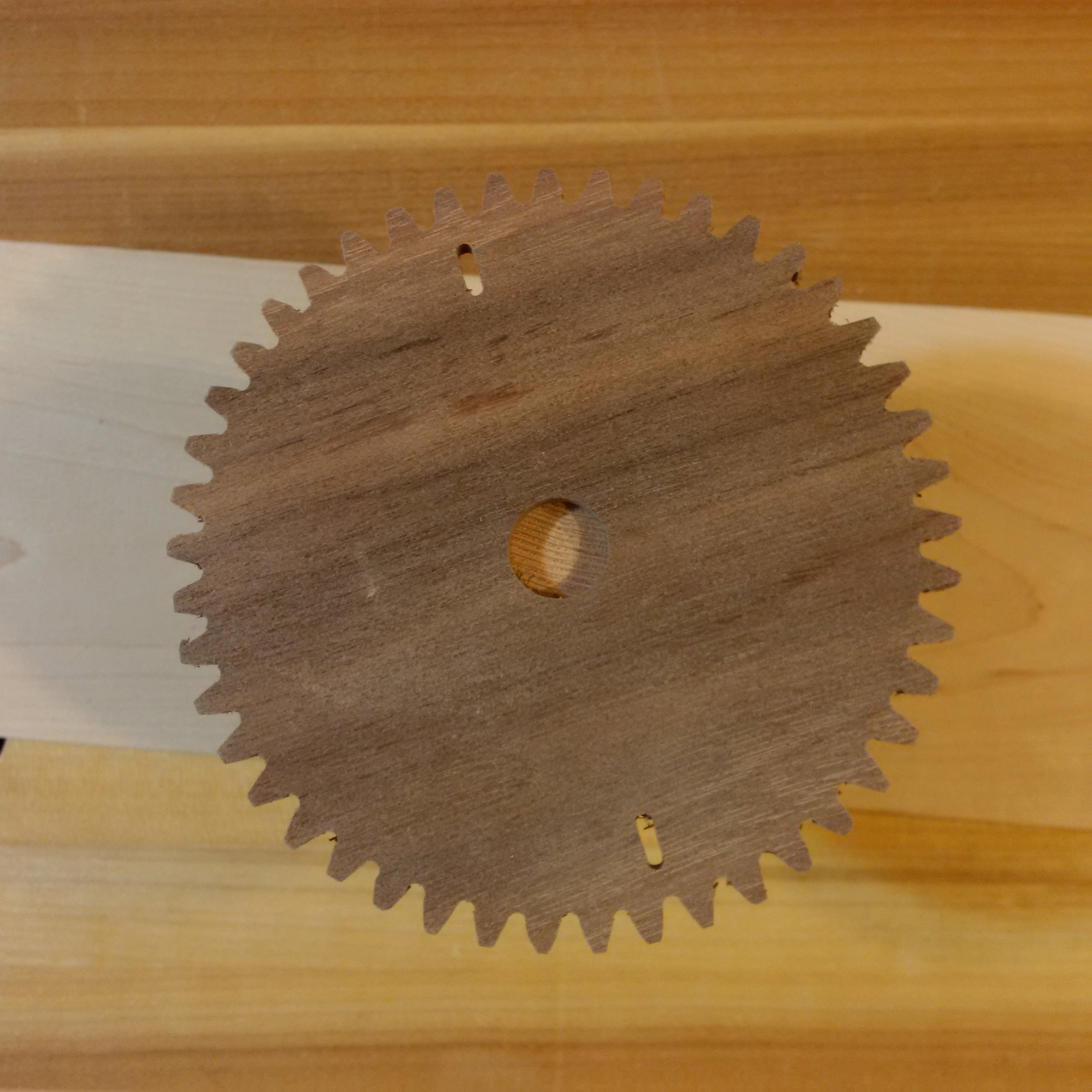
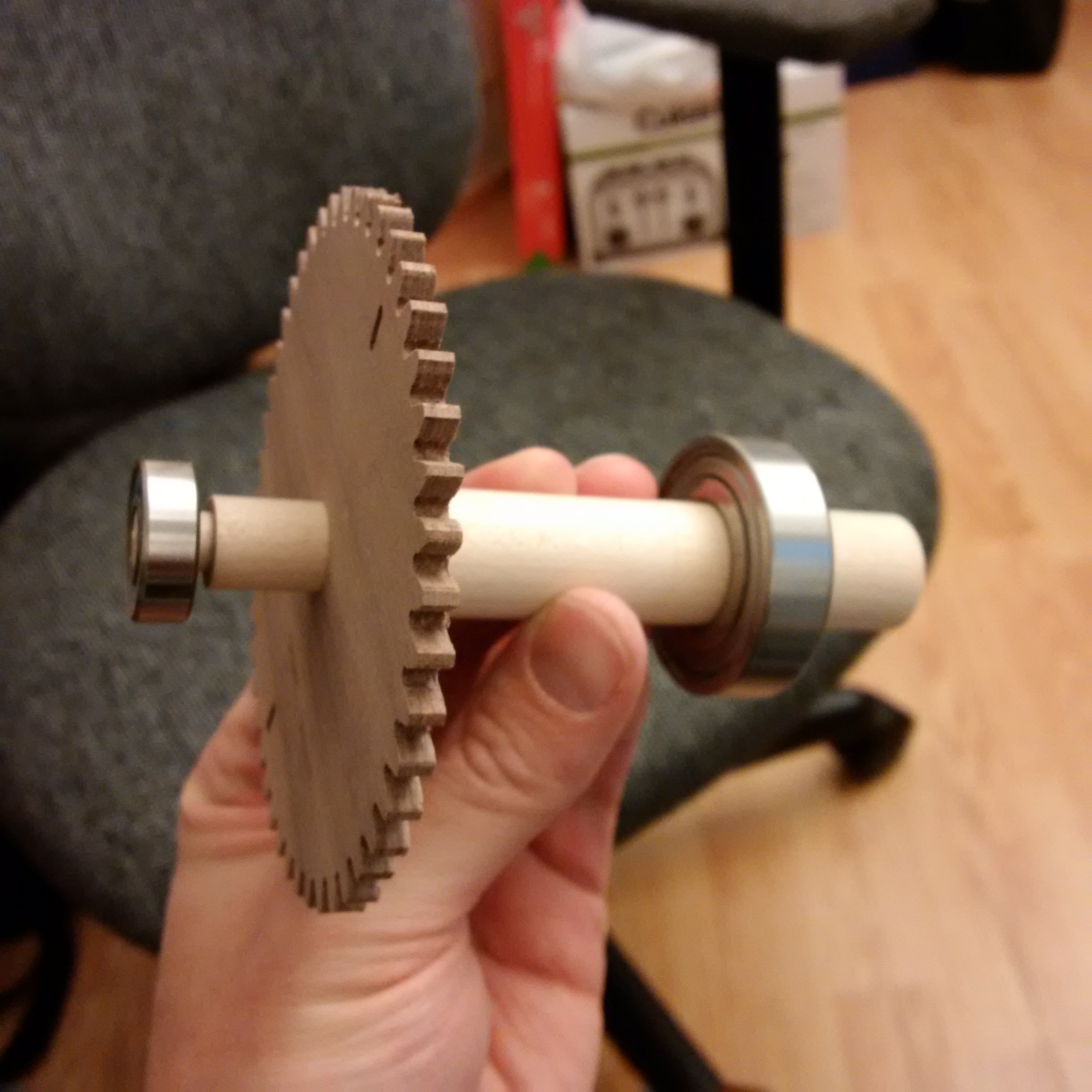
I chiseled in a couple of keyways into the shaft and made a matching collar that I glued on to the gear. Finally the gear is held in place by a little cup that goes over the shaft and is in turn held in place by the bearing. Lots of little pieces to get this done. It didn't take too long over all but it felt like a real slog to get through it.
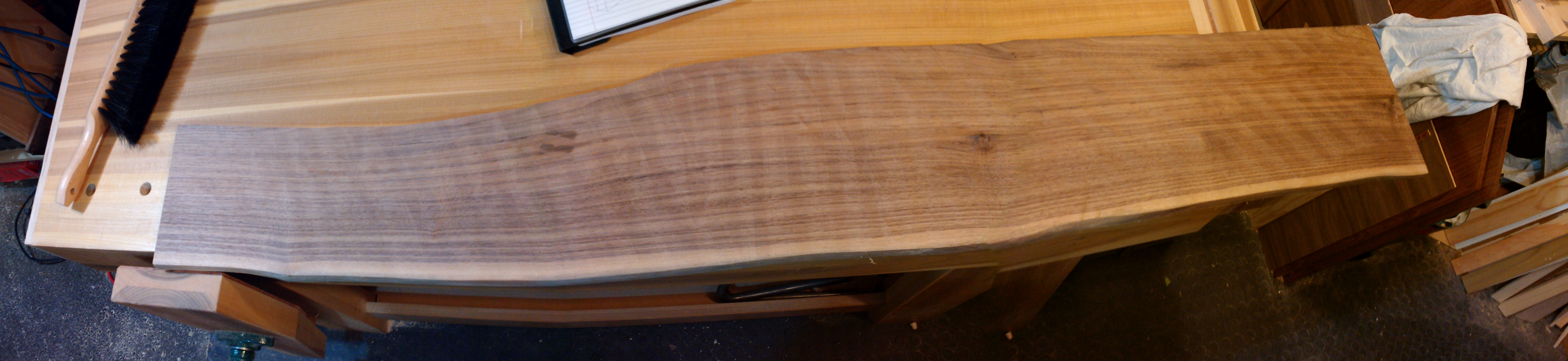
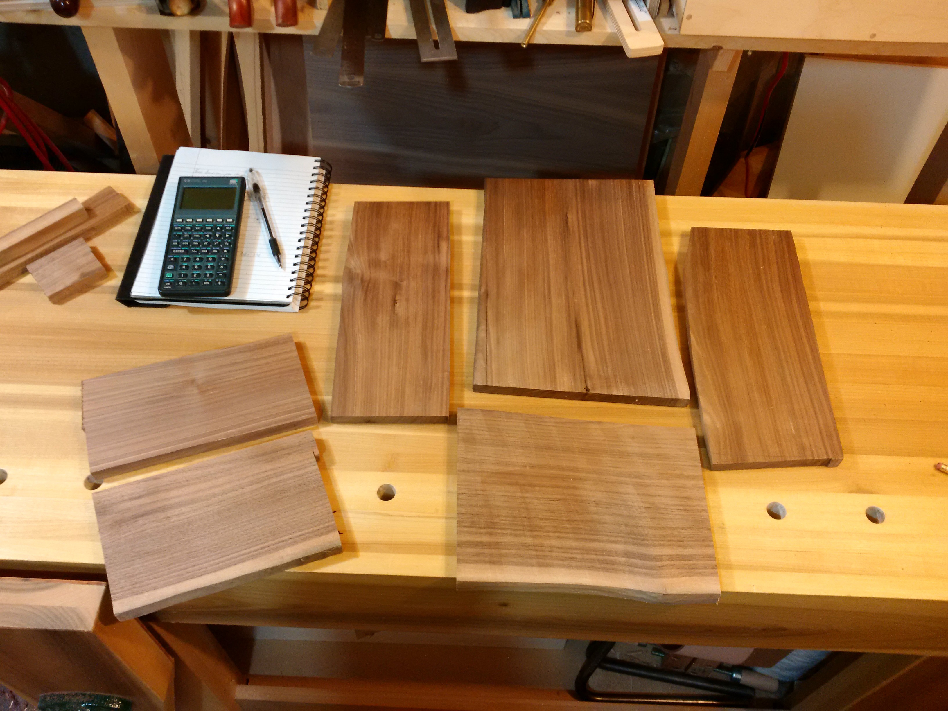
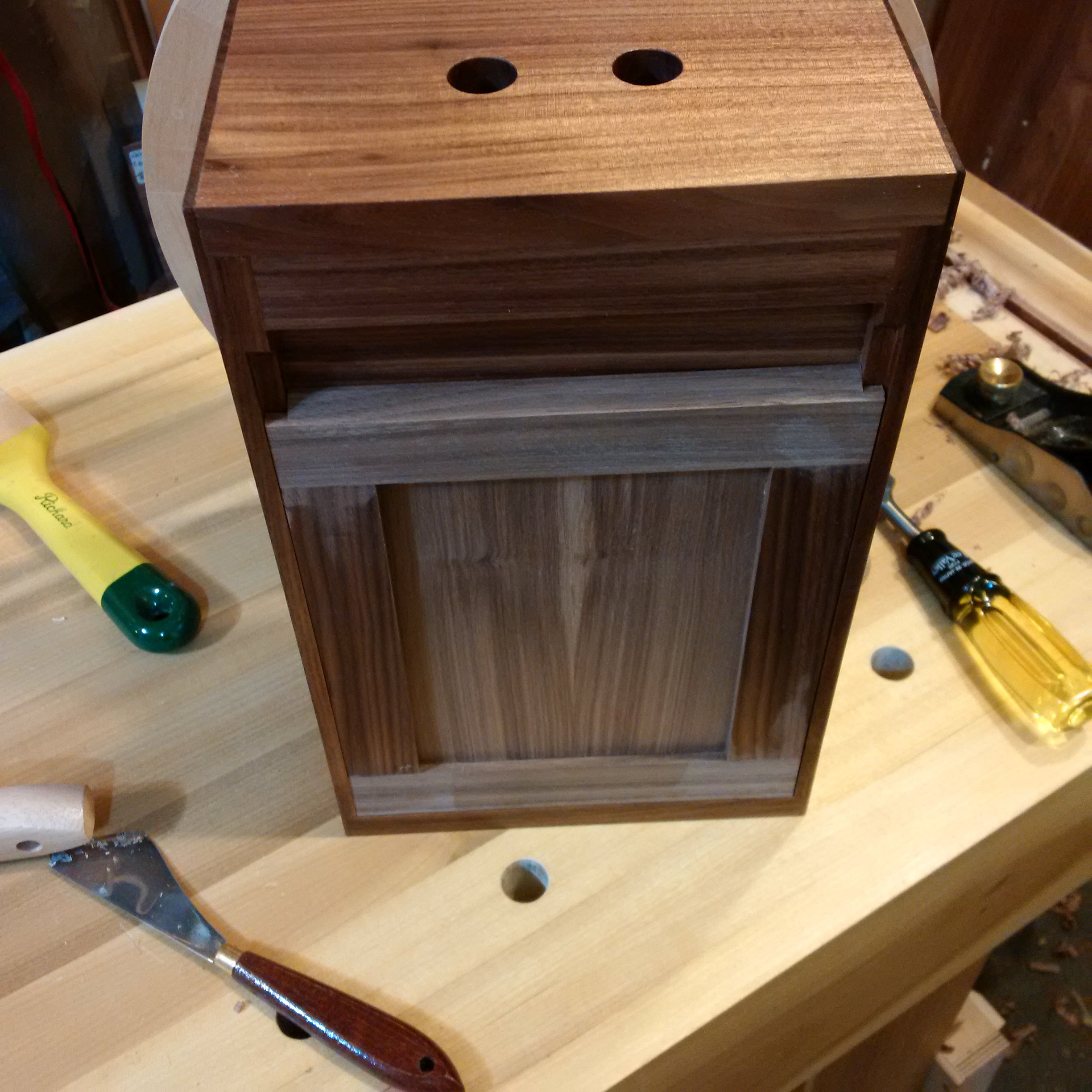
The box. At this point I it was shaping up and I wanted to have something nice to put the mechanics in. There was a board that I had picked up a year or two earlier at the local wood store. It was a nice piece of walnut which was quarter sawn, had really straight grain and had a bit of live edge. I really liked the piece but had not found a suitable project till this one. Luckily I was able to get all the pieces out of it.
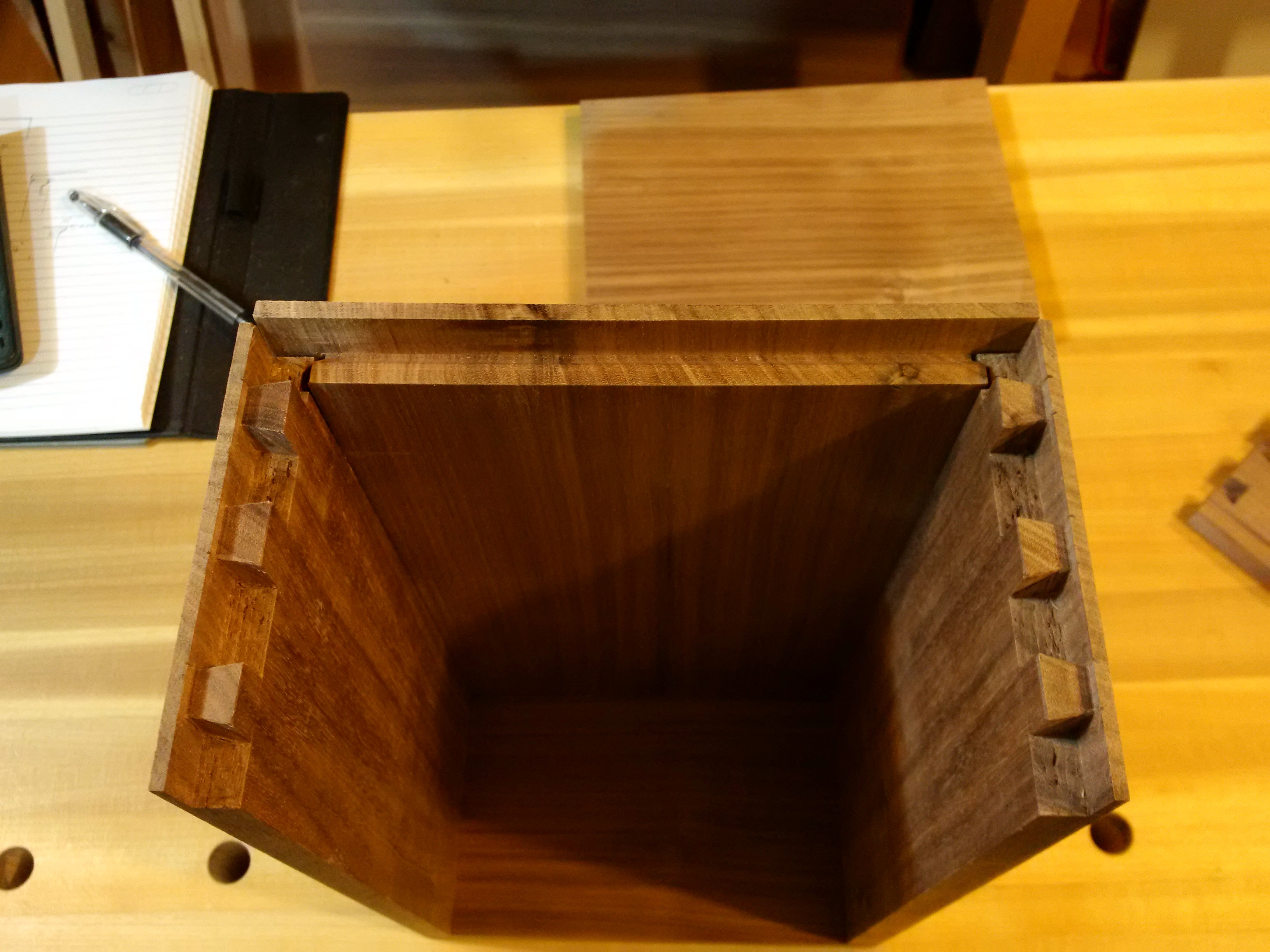
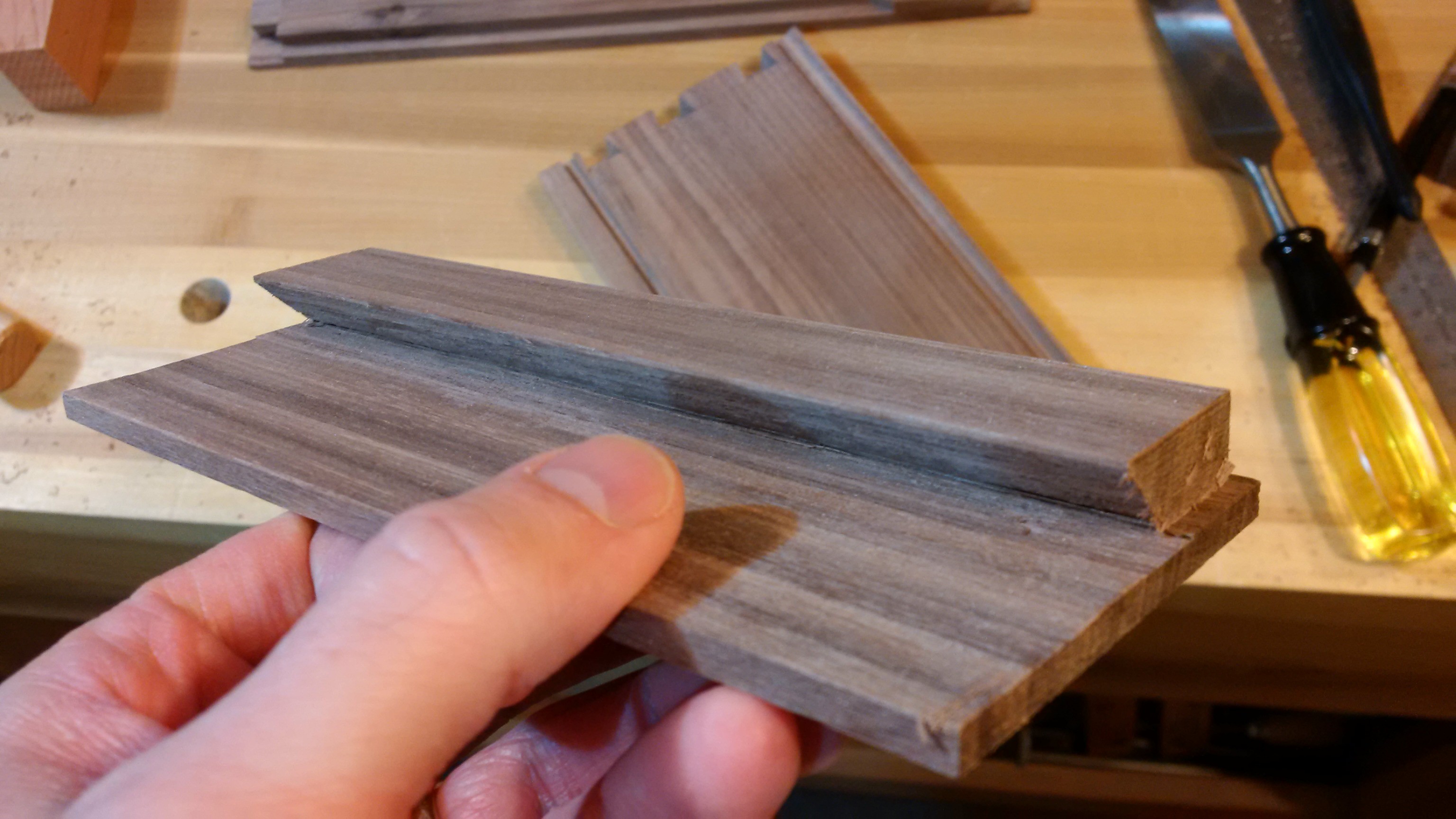
For this piece I wanted to keep a really clean look so I decided to go with full blind dovetails. They take a little bit of work to cut but they have the _really_ big advantage of being sturdy enough to hold everything together before glue up. This let me place components, brackets and things while I could still take it apart and work on separate panels. The top, bottom and sides got the dovetails while the front was a panel that locked in.

I wanted the clock to be usable free standing or hanging on the wall. To accommodate hanging I added a small french cleat in the back.
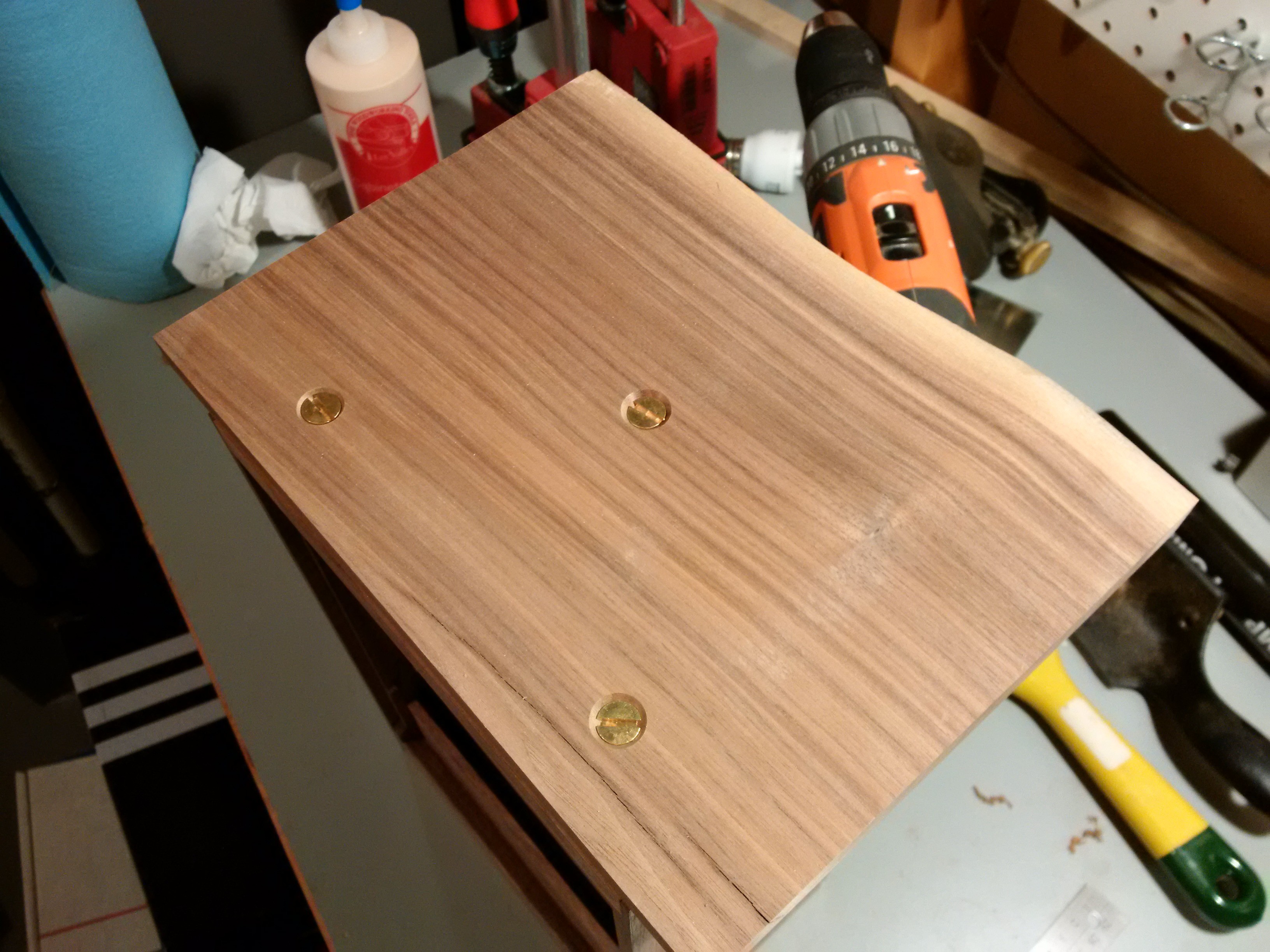
I knew that I would need to have the various brackets and things inside the clock removable as I made different pieces and tried to fit them in. To do this I drilled and tapped small blocks and glued them to the sides. This let me use little bolts instead of screws. It takes a little longer but they are really nice to use.

The center of mass for the clock was pretty near the front edge of the box so it needed a longer base. I thought it might look a little odd if it was hung so I attached it with three bolts. I was happy to have a chance to use a bit of that live edge here.
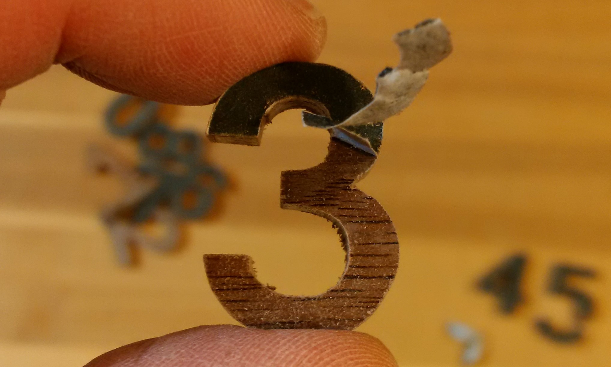
The outer ring still needed the numbers so I cut a set out on the scroll saw. I'd probably buy a set next time. They turned out nicely but took a bunch of fiddling.

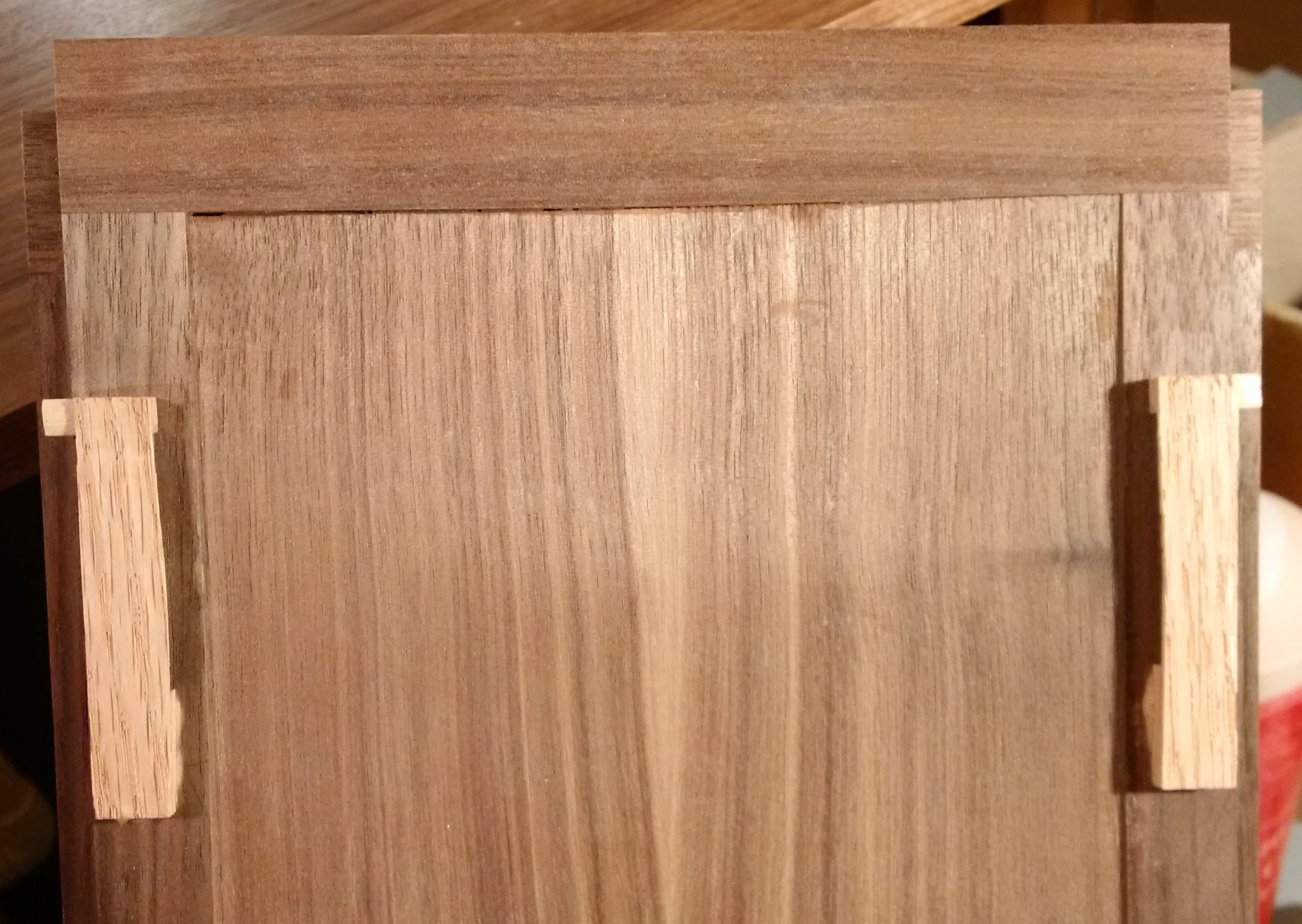
The back panel drops into a little groove at the bottom and at the top there are a couple of flexible tabs that pull the top in tight. The first panel fit nicely but then warped badly. The second attempt went with an inset panel of a couple small book matched pieces.
I chose to use tung oil as a finish. It is easy to apply but takes quite a long time between coats.
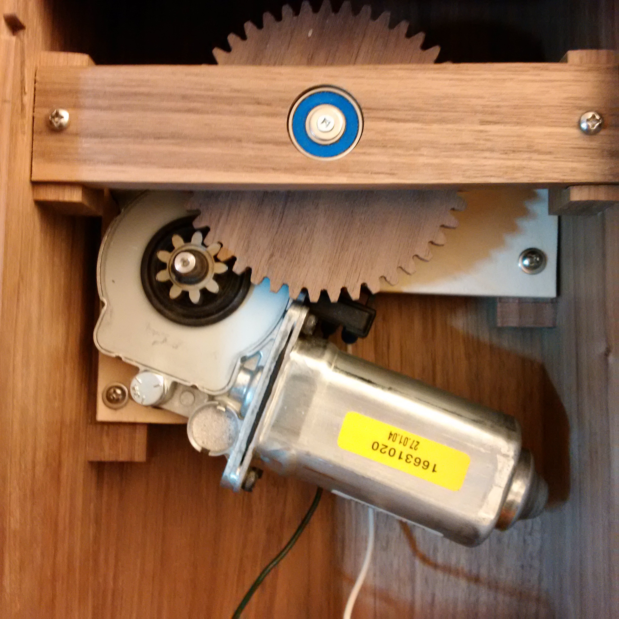
To this point in the project most of the materials were from things I already had. The walnut, maple, hourglass, even the bearings. This drove me to continue with that theme for the mechanics. I needed a motor that was both quiet and had good torque. I had previously picked up a car door window motor to experiment with and this (mostly) fit the bill. The main downside to it is that it needs a full amp to just get spinning. The bracket for the motor was made from birch plywood and mounted similarly to the axle bracket.
When I was tossing ideas around for how to keep time, most of them involved using a microcontroller and a battery backed RTC of some sort. The problem with that was that I needed to add some kind of user interface to set the time. It finally dawned on me that a cheap wrist watch had everything I needed: a display of the time, buttons for setting it and a RTC. Since the main clock just needs to be activated on the top of the hour I tapped into the speaker and set the watch to generate an hourly chime. I wanted the watch to be easily set and have the battery changed without hassle so I used a USB connector to mount it as well as get the chime signal out. Some copper slug tape and Kapton tape were used in place of the piezo speaker.

At this point, using a little micro would have been a clean way to go but I wanted to stick with the "parts on hand" theme. What I needed was a way to drive a MOSFET to engage the motor when there was a signal from the watch and then stop it when the photo sensor detects the slot. I also had to be careful that the circuit didn't draw too much current when idle or the batteries wouldn't last. I ended up settling on using a quad op amp as the basis for the circuit. There are two capacitor - resistor pairs that are used as a timer (much like a 555.) Both get charged when the chime signal comes in. The long period cap is compared to a reference and turns the motor on. The short period cap is used to disable the optical sensor briefly so the current slot has a chance to move past. When the sensor is triggered, the long period capacitor is drained and the motor shuts off.
Once I had the values tested and working on a breadboard I soldered them up deadbug style, retested and then coated in epoxy. I used some heavy gauge copper for a bit of structural support.
I had a rough idea for where the sensor would be when I glued the shaft in but left a slot in the mounting bracket so that I could tweak the vertical position.
I felt that the clock also needed a switch to turn it off if it wasn't going to be used for a while. To not spoil the clean look I wanted to make a switch that was flush with the box. I also wanted a nice smooth but positive feel. After trying a few different options I went with on/off buttons in the top. I used some spring from an old printer which kept the buttons held up and a rocker switch. Really happy how this part turned out.
The battery pack was a big pile of fail. I had planned on using 5 D cells which turned the motor at a reasonable speed and would fit across the bottom of the clock. The spacing was getting pretty tight at this point but I managed to rig up a battery holder for them.
It turns out that the D cells had way more voltage drop than I had planned for under the load of the motor and it simply would not work correctly (stopped too soon IIRC.) I had to fix that up away from home so I went ahead and bought two 4 AA cell holders since NiMH batteries will easily source the required current. I had not tested the circuit at 9V and it would skip forward after briefly stopping at vertical. Out of time, I simply made a dummy battery with more of that copper tape to reduce the number of cells to 7. Seems I missed taking a picture of that setup.

That hourglass was originally planned as a present for my sister... roughly 25 years ago. So it took a while longer than expected but it did get a few upgrades in the design. ;)