 Markus Dieterle
The Idea
After watching Ladyada's intro video to the Pi Zero contest (see it here if you haven't already), I was thinking about what might be an interesting project with a Raspberry Pi Zero.
Somehow the idea for a mobile text reader for visually impaired people popped up in my head. While I currently don't have much contact with such people, I actually got to know one blind guy very well several years ago. He was a friend and colleague of my father, and we often visited him and his family. He was living a full life and clearly enjoying every bit even in spite of his blindness, so that was a pretty positive impression I got.
Years later, when I started to study at the University of Karlsruhe, we had a group of blind people studying computer sciences and other topics along with the rest of the students. At that time it was a prototype program that incorporated new hard- and software, like mobile braille terminal laptops, OCR etc. and special oral exams into a new offering for enabling people with severe visual impairments to study the same thinks as everyone else.
Due to that, my first idea was to produce something similar - a small mobile unit with a camera and integrated OCR and a mini braille display output. Looking at the braille display technology though, I realised that a usable electro-mechanical device like that would need more time than I would have if I wanted to enter this project into the Hackaday / Adafruit Pi Zero contest.
So instead of adding a braille display, I chose to use text-to-speech conversion and audio output instead.
Options for Expansions or Variations
Thinking about different components and build variations, there are several options to expand the basic unit or turn the construction into a different variation, depending on individual needs. Here are some of the possibilities I've come up with so far:
- a fixed stand with a slide-in mechanic that the mobile text reader can be connected to - allowing easier battery reloading, easier book scanning, and adding the option of hooking it up to a TV or monitor for zoomed text viewing
- expanding the software to incorporate a text library (that partially might have been created using the OCR software) with an audio interface, turning it into an audio text player
- adding a braille display (at least for a non-mobile usage) for text output, with the option of audio output of displayed lines for learning
- adding an LCD or OLED display for turning it into a mobile electronic magnifying glass
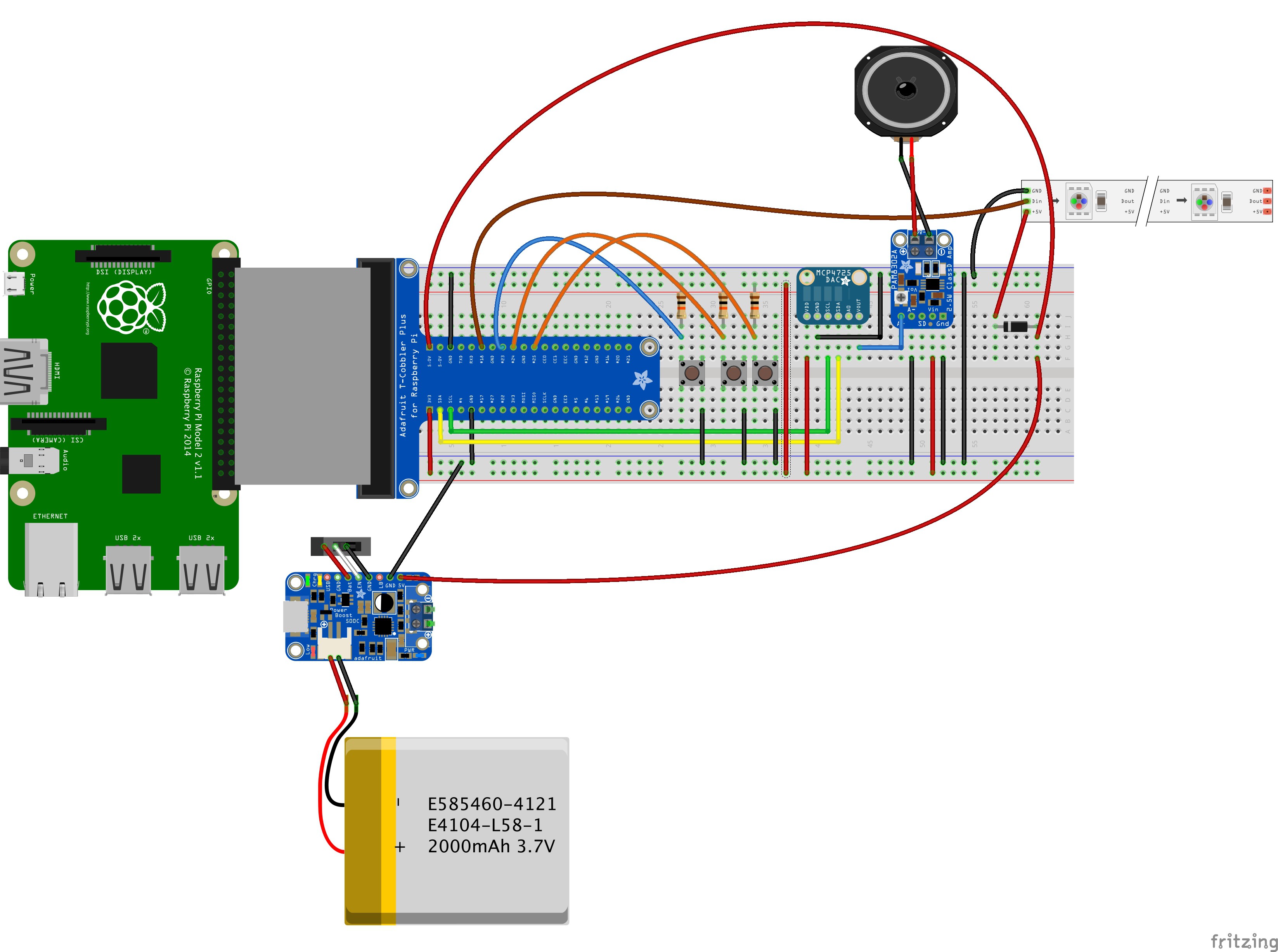
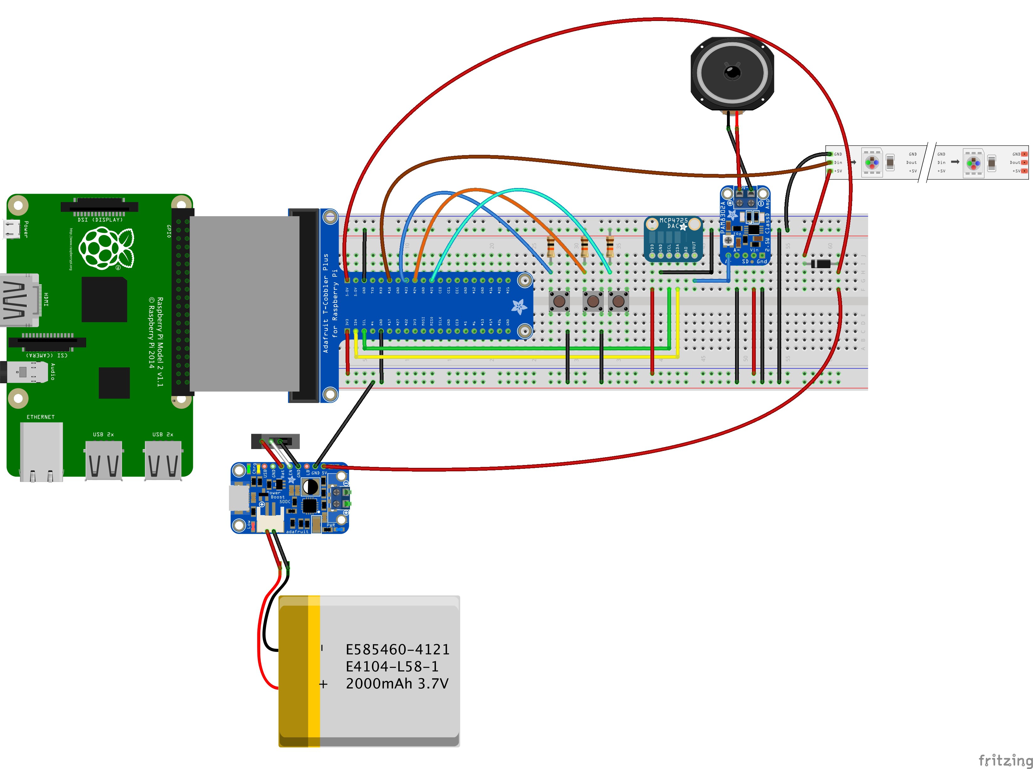
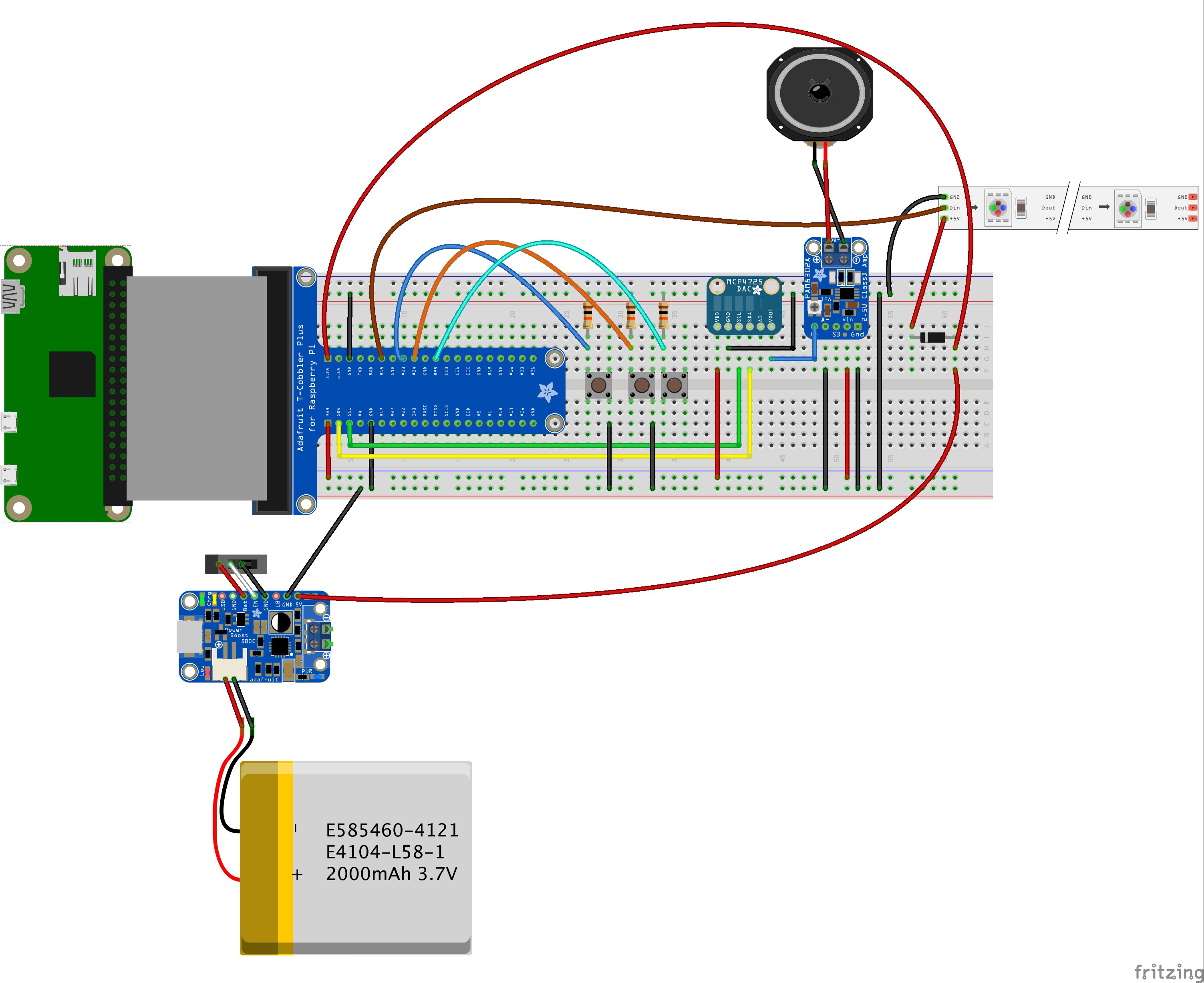
Hardware components
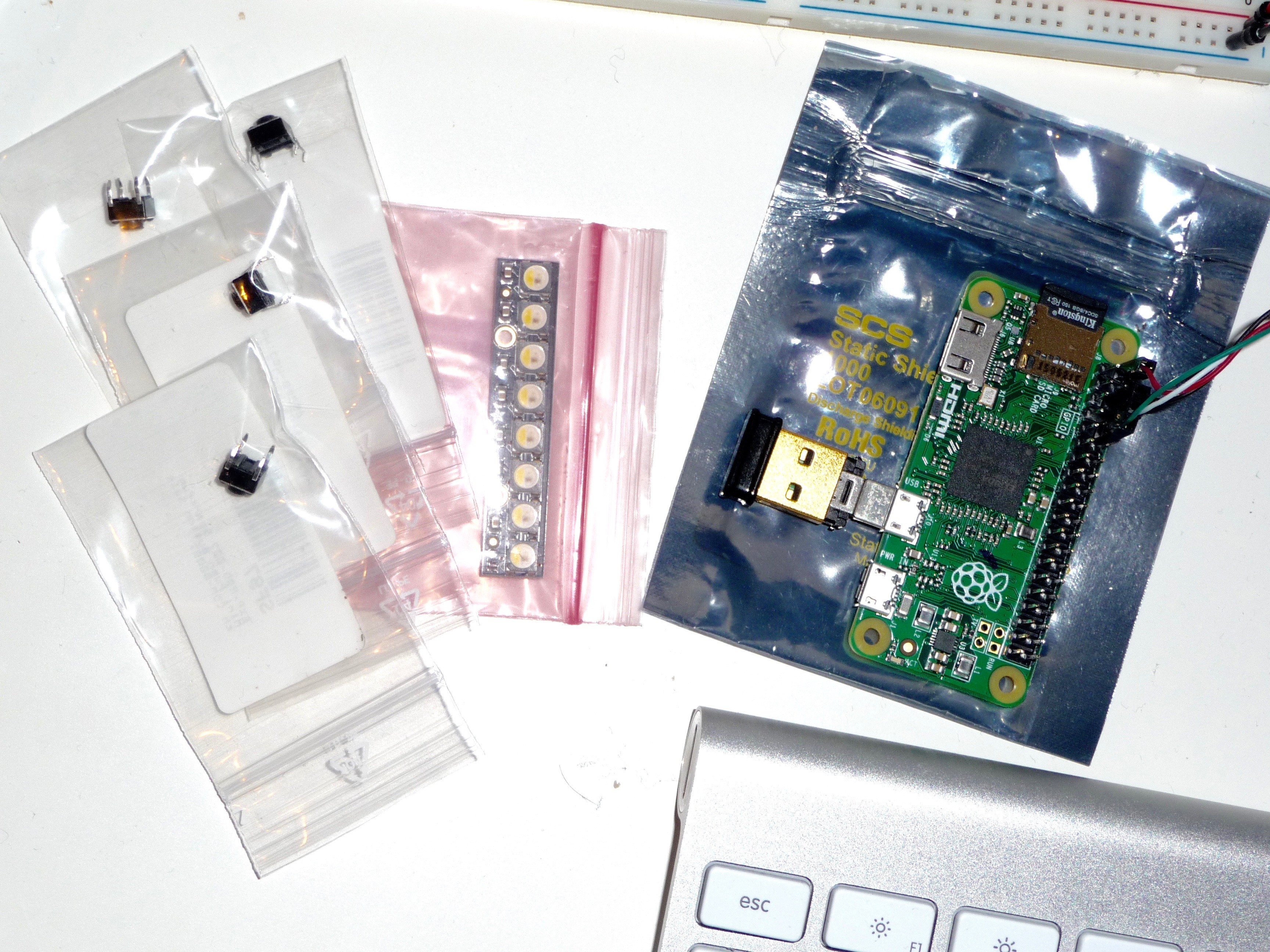
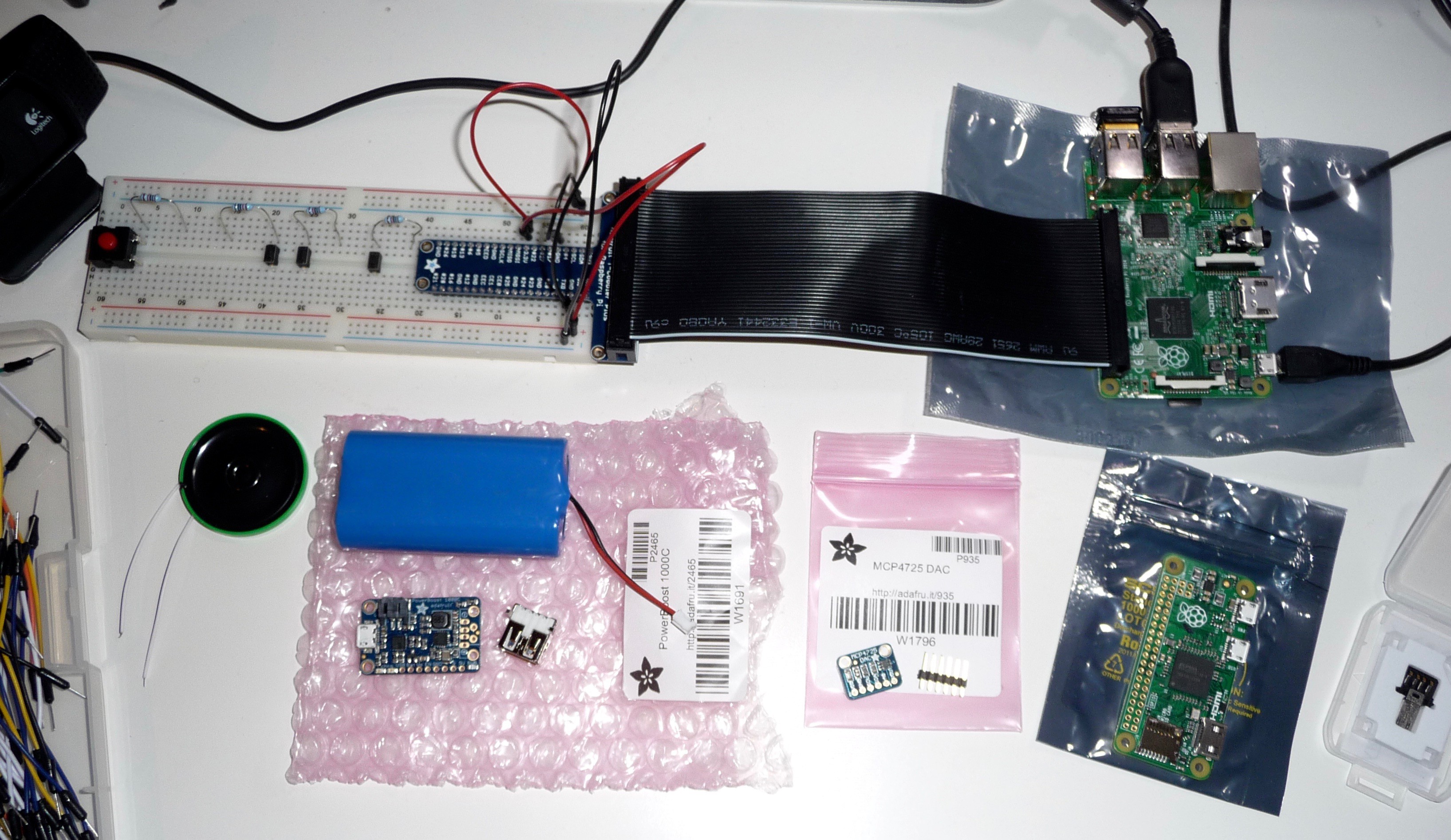
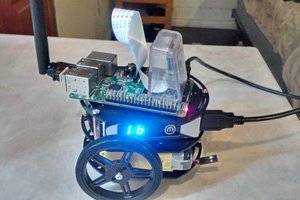
The necessary hardware components for the basic device should be the following:
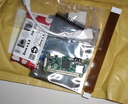
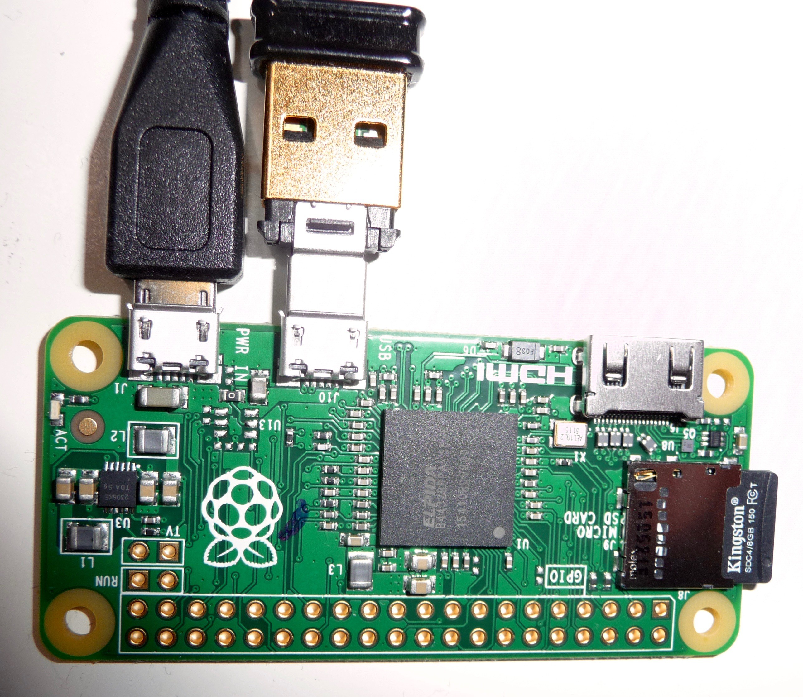
- Raspberry Pi (Zero or other)
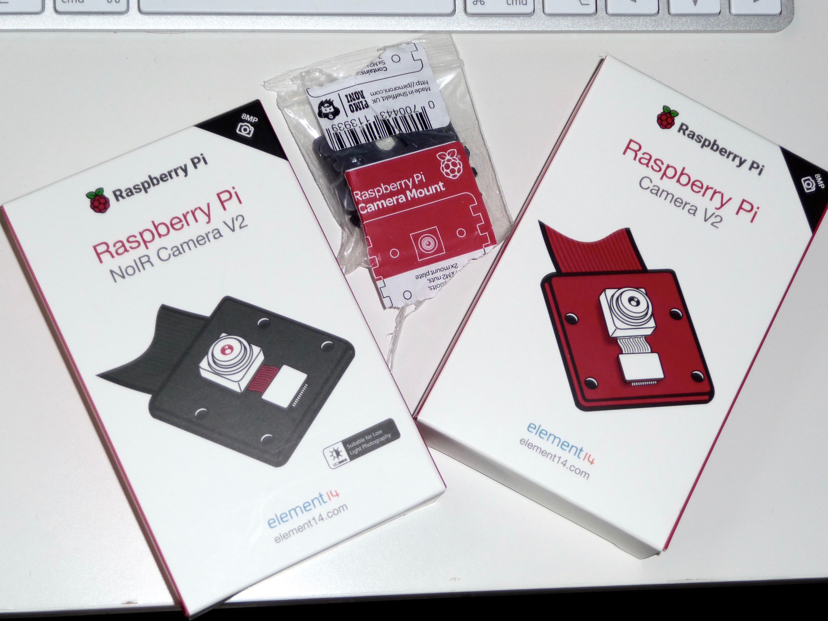
- Pi Camera module or USB webcam
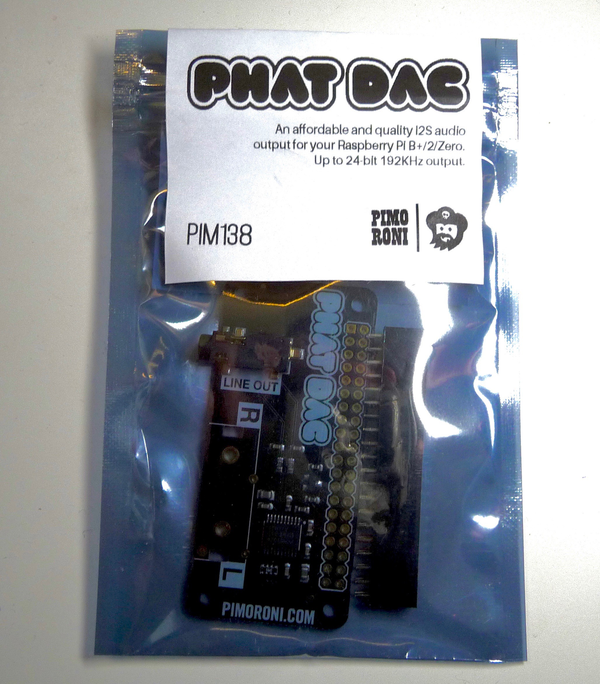
- for the Pi Zero: DAC board for quality audio output (optional for the other models as those have audio output included)
- rechargeable battery
- recharging circuitry for the battery
- speaker for audio output (optional)
- ultrasonic or IR distance sensor (optional)
- buttons for scan activation, volume control, mode switching etc. (depending on intended software and hardware combination)
- additional SD card reader/writer breakout board for "external" image and text storage
- optional vibration motor for feedback from distance measurements
Software components
The basic device should (at least) be able to do the following things:
- taking images and storing them onto an SD card
- running OCR processing in order to convert the images into text files
- creating audio output from the text files using text-to-speech conversion
Thankfully, those main functions have already been implemented by several people in different projects.
Camera function
Greg Holloway has documented his SnapPicam project on the Adafruit Learning system: https://learn.adafruit.com/snappicam-raspberry-pi-camera
This project already includes the first block of functionality I need here - the ability to take pictures on a button-press and store them as an image file.
There are other documentations available elsewhere on how to install and use the Raspberry Pi camera. Concerning energy usage, I'd prefer using the...
Read more »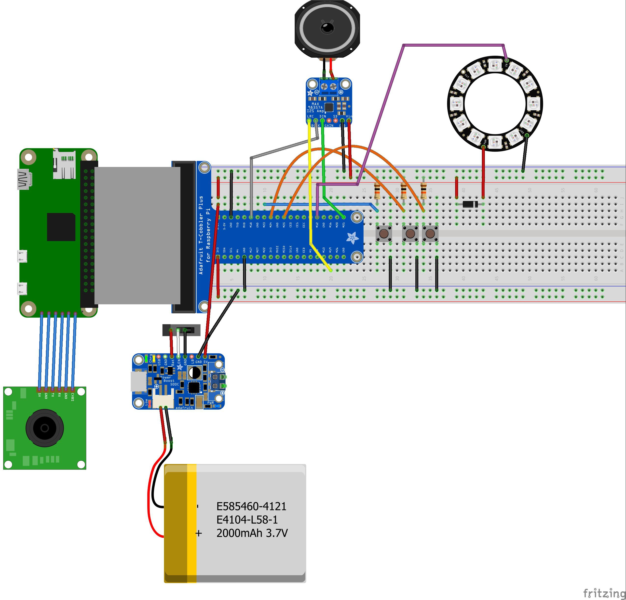


 Brenda Armour
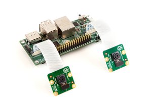
 Eugene
 Ray Patel
 danielmcgraw
hi markus! I just found your project and I am working on a comperable project. this is the reason why i would really like to share some experiences with you! u mentioned that u made ur studies in karlsruhe: do u speak german? My goal is to build completly automatic glasses that can scan text and give it out as a audio. I am really sry for this confused text but I just wanted to contact u. and sry for my really bad english
sincerely
granit