 Muth
MuthI finally manage to solder the TQFP 80 package of the PIC on the breakout board. Everything seems alright, I can program the chip with the Pickit.
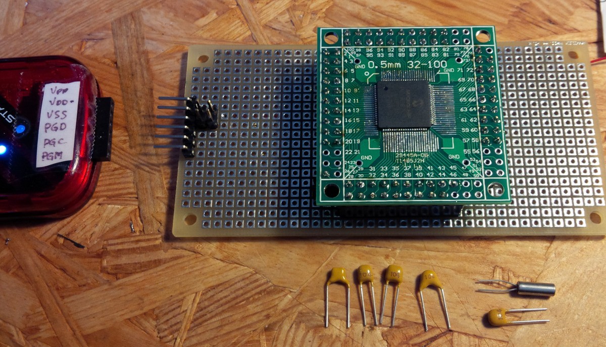
It took me some time to figure out why the RTC was not working. I took a scope and checked the 32.768KHz second external oscillator, and could see a sine wave appearing. And that was the point. The signal appears when I put the scope probe on the quartz pin. The error was a wrong capacitor value. Somehow I put a 100nF cap instead of a 12pF for one of the quartz surrounding grounded capacitors. I don't know how the probe change the circuits impedance and makes it start oscillating, but with the correct capacitor I could now see the RTC running.
A nice thing with the PIC 18F87K90 (let's call it the PIC...) is it can drive 48 LCD segments in static. Which is exactly all the segment I have on the 6 panels. 7 segments for the character and one dot. But... and it seems there is often a but with Microchip... But on the 48 pins able to drive LCD segments, one is multiplexed with the RTC oscillator... (pin 35 mixed SOSCI and SEG32)
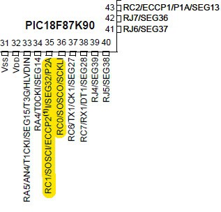
Well, I decided to get rid of one dot ;)
Right now I connected 2 digits and they display the seconds of the RTC. It's working great however I should wait all segments are connected. I'm sure I will have to fine tune the Pic parameters to have nice contrast. After that, perhaps there is nice digit transition to make ? In addition, I have to think of time adjustment buttons.
Discussions
Become a Hackaday.io Member
Create an account to leave a comment. Already have an account? Log In.