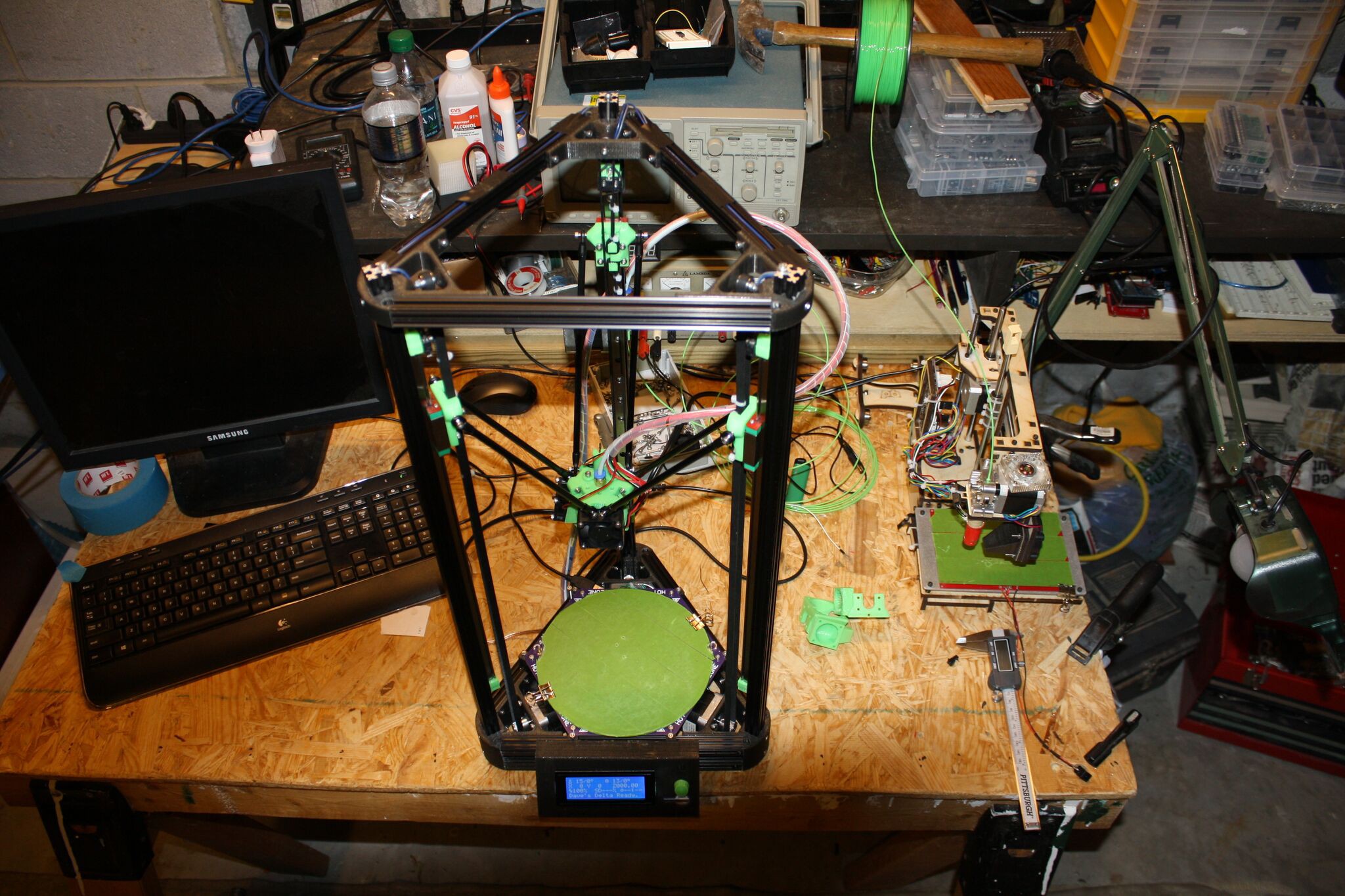
Close
0%
0%

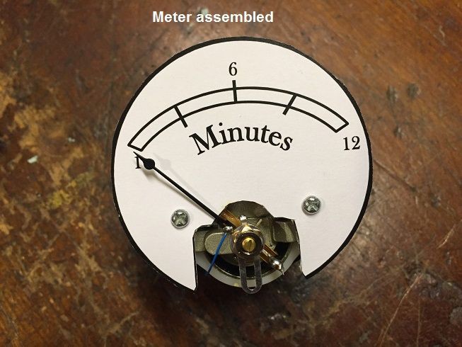
Not another D'Arsonval Movement clock

Another clock based on D'Arsonval Movements mk

Similar projects worth following
After seeing a couple of these around the internet, I decided to build one for myself. It is based around three 0-5v D'arsonval movements I found on Ebay. The meters will be driven by an ATMEGA 328 programmed under the Arduino environment and time kept by a DS1307 RTC. Backlighting is accomplished by the use of WS2812 RGB LEDS. I am planning on setting the time by selecting units with a rotary switch (Hours, Minutes, or Seconds) and then setting the value with a potentiometer. The front panel was made out of 1/8" birch plywood cut on a stock KD-40 laser/engraver using LaserDRW. I haven't gotten to upgrading it yet :(. The led domes for the AM and Power Indicators will also be homebrewed on a Kossel DeltaBot. I'm presently contemplating putting an esp8266 on it to sync time and push a virtual version as a web page.

See build log for details

pixels.ino

Pixel driver

plain - 718.00 bytes - 06/05/2016 at 21:45

Download

FSM.ino

The Finite State Machine that runs the clock

plain - 3.50 kB - 06/05/2016 at 21:45

Download

davesClock.ino

Main sketch for the clock

plain - 3.81 kB - 06/05/2016 at 21:45

Download

RTC.ino

Realtime clock driver

plain - 1.96 kB - 06/05/2016 at 21:45

Download

box t and b.lyz

Laser cutter file (LaserDRW) for top and bottom of the box

lyz - 8.81 kB - 02/18/2016 at 04:11

Download

View all 9 files

  • 1 × ATMEGA 328
  • 2 × 22pF Capacitor
  • 1 × 16MHz Crystal
  • 3 × DC 05V Round Analog Voltmeter Voltage Panel meter DH62 with Shunt http://r.ebay.com/TFlw4T Electronic Components / Misc. Electronic Components
  • 1 × 22K ohSingle Turn Rotary Linear Taper Carbon Potentiometer Pot http://r.ebay.com/HXBFV0

View all 10 components

  • It's Finished

    dnk1706/05/2016 at 15:08 0 comments

    Sorry for the long delay in finishing up this blog. But the project is finally finished.

    I will be adding some additional photos and uploading the source code to Github.

    At the end of the day it turned out ok, I need to replace the seconds meter and look into the minutes meter. It appears that the cheap(actually not so cheap) meters from China are of pretty poor quality.

  • 3D Printing LED Diffusers

    dnk1703/03/2016 at 03:17 0 comments

    If you look at the photos of the face plate there are two holes for LEDs. One for power and one for AM indication. A while back I had made a pretty cool RGB LED color cube, using WS2812B LEDS. I had printed out a box on my homemade deltabot using clear PLA and it worked out pretty good. So the thought was to do the same thing for the LED diffusers.

    I hadn't used the deltabot for while, so it took a day or two to get it dialed back in. But it is working great now. Below is an older photo of my bench at home, you can see the Delta in the foreground. To the right you can also see my PrinterBot Simple that I used to make the Delta.

    It also took me a little bit to re-learn sketch up. Great program, but the learning curve can take a while til you figure out the best way to do things. I ended up drawing profiles and then using the follow me tool to spin it around a circle.

    Quick hint I learned. Sketch up has trouble with "follow me" and features smaller than 1mm. So when I first drew them, I had done it scale and had some trouble with missing surfaces. I simply scaled the whole drawing up by 10x, did the "follow me" then scaled back by 0.1 and all was good. I printed them out with a shell thickness of 2mm and 40% infill. They ended up looking and fitting great.

    I now need to cut a square hole in the side of the box to accommodate the USB Female B connector. I am going to connect a usb to serial converter and then use it both power and program the clock.

  • Minor Updates

    dnk1702/23/2016 at 00:27 0 comments

    Took the weekend to do some finishing on the box. I ended up using a golden pecan stain on the new face plate. I put a couple of coats on to get a nice rich finish. I did notice that I also make another rookie mistake, the grain on the once side goes in a different direction that the other sides, its not a big deal, but was avoidable.... I have also been able to get 3 nice coats of polyurethane on it. It takes awhile but it sure does make it look purdy. So far I have 3 coats on it. I do one at night and then one in the morning. I am thinking I will two more coats on it, and that should give it a real nice finish.

    For grins I have added my original design drawings.

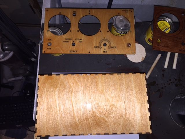
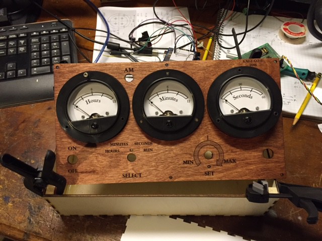
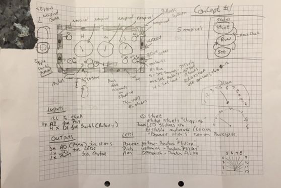
    *The corner is ripped off to protect the innocent.

  • Mid Week Break

    dnk1702/19/2016 at 02:35 0 comments

    Not much today. After looking at the face plate, I decided I did not like the mahogany stain and a couple of of other little things, so I made a new face plate tonight. 1/2 hour and a new face plate! Got to love the laser cutter. Did some sanding also, I just the feel of a well sanded piece of wood. :)

    I also started the schematic just for documentation. At this point I am doing simple point to point wiring on a proto-board. I might do a board later. I wanted to try out using the laser to make one. I had read where you spray paint or use sharpie to cover the board. Then use the laser to burn it away, then etch, and then even use the laser to cut through holes and routes (if you use a paper based pcb vs FR4).

    The goal for this weekend is to finish up the proto-board and stain the box. With the clear coat and work on the finishing the code next week.

  • Making the box

    dnk1702/18/2016 at 03:55 0 comments

    My wife makes fun of me for all the "Chinese" packages I get in the mail. Well today was a banner day! When I got home there were three little yellow envelopes with Chinese characters on them. The first was a cheap ($20) blue tooth smart watch (I'm not sure what I will do with it), and a flow switch. But more importantly a new laser head for my K40 arrived. It is nothing special, just one of the the generic machined 18mm air assist heads. I bought it as a replacement for my 3d printed one from Thingiverse.com. The 3D printed one worked great for quite some time, but after a couple of flareups it was starting to look worse for wear and it was time for an upgrade.

    New Air Assist Head

    I have been using an air assist for quite some time now and I have to say is it makes a huge difference in the cutting ability and edge quality. Adding an air assist should be every-bodies first upgrade to any K40.

    Old air assist

    Since I was a little late getting home from work I wasn't planning on spending much time on clock tonight. But I wanted to at least look into what I needed to do to install the new air assist.

    So I fed the kids, pet the dogs, kissed my wife and headed into the basement for a little bit and to put some things away. Installing the air assist looked to be pretty straight forward, so I thought I would just do it. Once I had it installed I needed to re-calibrate the optical path to compensate for any changes needed for the new head. Long story short, so much for not spending much time in the basement. A couple of hours later I had drawn up and made the rest of the cabinet for the clock.

    The box was designed in LaserDRW (files attached) an cut out on the cutter (with the new air assist :). It's a simple box with 10mm x 3mm tabs used for joinery. Above is a picture of it glued up and clamped. On the table are some card stock prototypes that I cut first to make sure of the design. Everything went well and the box went together easy. But I did make a rookie mistake , in my excitement instead of measuring how deep I needed the box to be to fit everything in, I took a guess and made it 70mm deep. I lucked out that the meters fit in OK, but it will be a little tight with the PCB in there also. But it should work, even though a little more space would have been nice.

    Oh I also rummaged around the basement and found some old Mahogany stain and used it on the face plate. Its a little red, but should look OK when clear coated. I am still debating about just cutting a new face plate and using a different stain.

  • The Meters

    dnk1702/16/2016 at 03:34 0 comments

    After looking around ebay I found a meter that was inexpensive and I thought would like good for an "old timey" clock.

    DC 05V Round Analog Voltmeter Voltage Panel meter DH62 Neednt with Shunt http://r.ebay.com/TFlw4T At $9.00 each with free shipping from China, I was a little hesitant on the quality. After about a week they showed up. First thing I did was test out the calibration. Well guess what it was pretty far off. All in all I had to do a number of modification to each meter. In order of execution.


    1. Open up the meter and remove the measurement panel
    2. Remove the crappy wiring and calibration resistor
    3. Drill a 1/4" hole in the middle of the back, so that a WS2812 LED can be mounted later
    4. Drill a 1/16" hole above the 1/4 hole for access to the 10Kohm 10 turn pot. To calibrate the needle
    5. Wire the negative terminal to the top side of the movement
    6. Connect the center and one of the wipers on the pot to the + Terminal
    7. Connect the other side of the pot to bottom side of the movement
    8. Put the new measurement panel on. Made in power point and printed out on cardstock
    9. Close it up.
    10. I then calibrated using an Arduino sketch were I type in a PWM value (0 to 255). Calibration consisted of setting the PWM to zero and then using the cam to set the zero point. I then set the PWM to 255 and adjusted the pot to full scale.

    /*
    Quick hack to test meters
    */
    #define OUTPIN  (5)
    char  pwm_val = 0x00;
    String in_cmd = "";
    
    
    void setup() {
      pinMode(OUTPIN, OUTPUT);
      Serial.begin(57600);
      Serial.println("Meter tester started");
      Serial.print("PWM out on pin ");
      Serial.println(OUTPIN);
      Serial.print("PWM initialized to: ");
      Serial.println(pwm_val, DEC);
      Serial.println();
      analogWrite(OUTPIN, pwm_val);
    }
    
    void loop() {
      while (Serial.available())
      {
        Serial.print("cmd] ");
        in_cmd = Serial.readString();
    
        pwm_val = in_cmd.toInt();
        Serial.println(in_cmd);
        Serial.print("PWM set to:");
        Serial.println(pwm_val, DEC);
        analogWrite(OUTPIN, pwm_val);
      }
    }

  • The Idea

    dnk1702/16/2016 at 02:54 0 comments

    I work at a largish industrial electronics company, and while the stuff we develop is pretty cool, most of it is related to communication infrastructure so its not what I would say is excessively FUN to design. So a number of us do home projects and often time try and outdo each other. So when a co-worker brought in a Nixie tube clock he built from a kit, I felt the need to one up him with an even geekier clock. Remembering that I had seen a couple of meter based clocks on here I decided to make one. At first I thought about doing it as fully geeked out steampunk. Even played around with building a piston type thing to simulate a steam engine. At the end I settled on just making it look vintage, so that I would have a fighting chance to get it done in a decent amount of time.

View all 7 project logs

Enjoy this project?

Share

Discussions

dnk17 wrote 02/16/2016 at 10:56 point

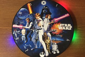
Funny never noticed it. I guess my brain just saw it as an analog clock. The project is still a work in progress, so its easy to swap out the panel. I will have to think about. I sort of like it as it is. Comments?

  Are you sure? yes | no

davedarko wrote 02/16/2016 at 08:31 point

how do you show something with more than 12minutes?

  Are you sure? yes | no

Similar Projects

Does this project spark your interest?

Become a member to follow this project and never miss any updates