 Arya
AryaI sometimes need to read and write SPI flash memory chips. Furthermore, I just got a task to re-flash a BIOS on a motherboard, so I had some additional motivation to make me a tool that does it. I've heard good things about FlashROM, it's a pretty versatile package which is open-source and supports many programming platforms, including Raspberry Pi.
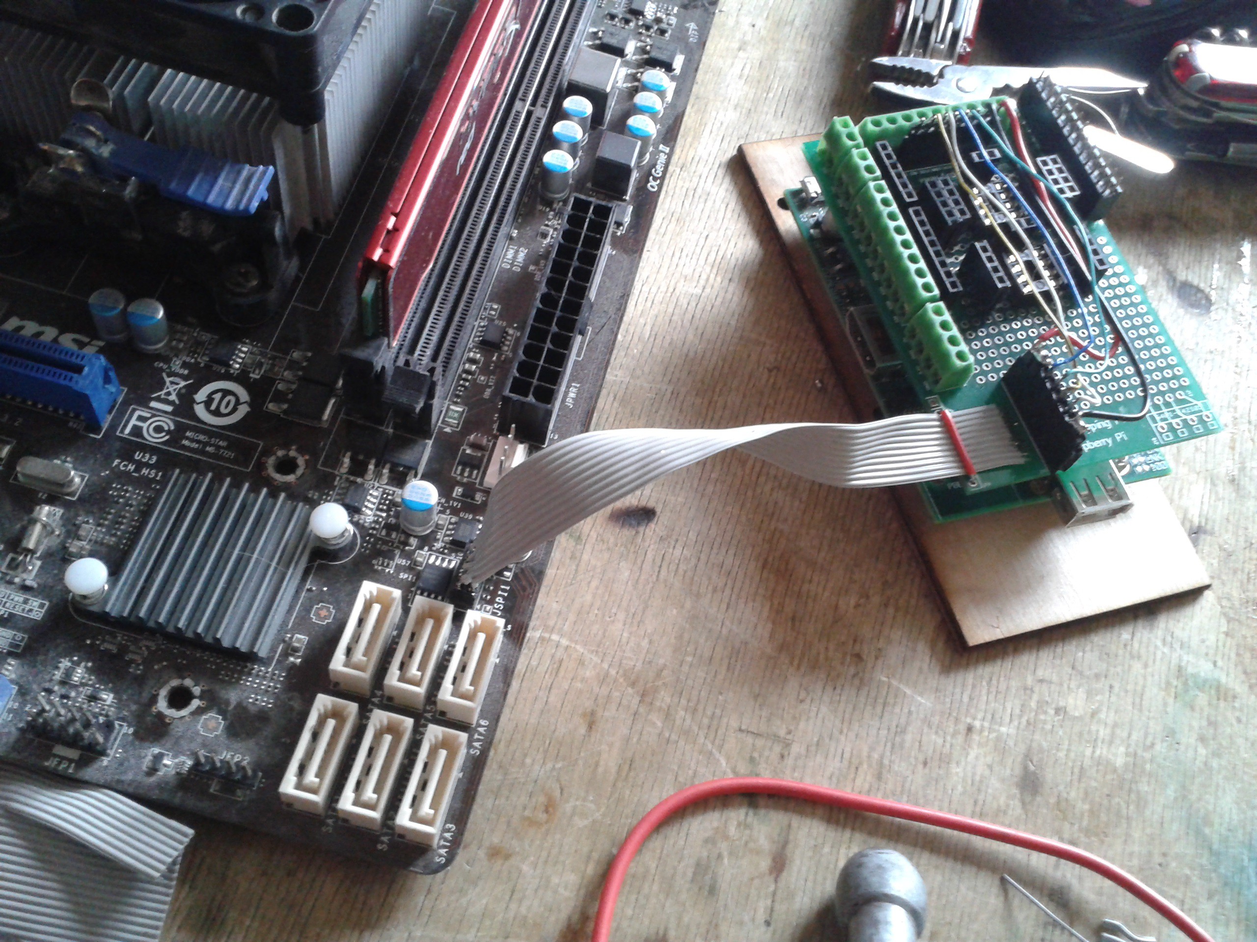
The motherboard (MSI FM2-A75MA-P33) had a SOIC SPI flash chip which was soldered on, but all the pins were available on a header, pinout for which seemed to be already reverse-engineered and available on the Internet. 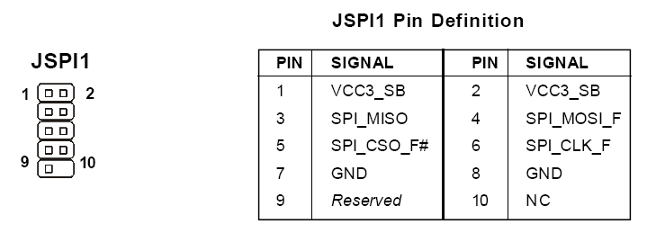 The header had 2MM spacing between pins, but I bought a corresponding connector for this and soldered a ribbon cable with proper spacing to it. I then soldered this cable to the prototyping shield I use and made a cable which'd connect it to the proper SPI&power pins.
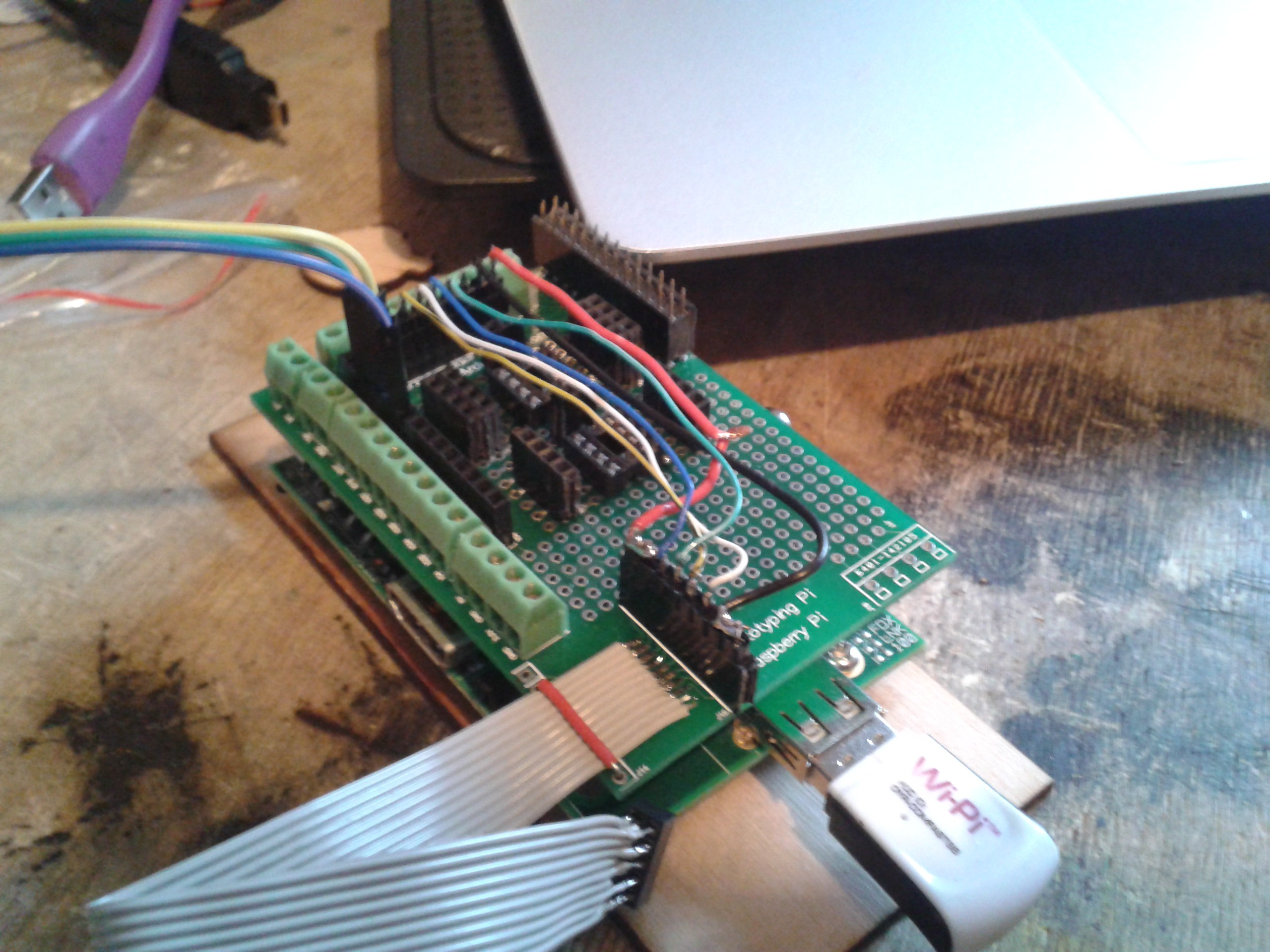
Next, I needed to download and compile flashrom. It was really fast, I just needed to apt-get some library dev versions. It also recognised the BIOS chip I connected to it, which was marvellous - it means it's able to communicate with the chip without any problems.
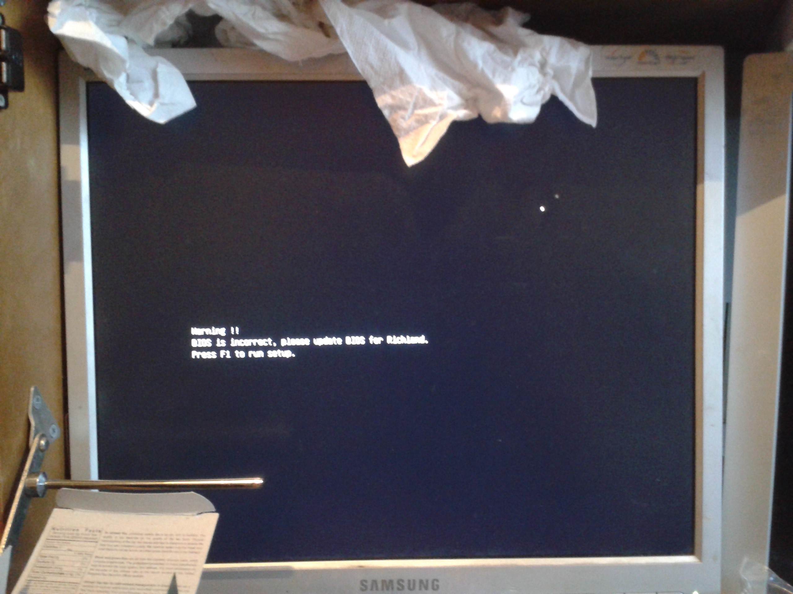
I read the chip's contents and, sure enough, it was erased - except for some areas. Seems like BIOS flashing process started, but never finished. I erased the chip and wrote an image I got on the MSI website (those bastards didn't provide proper recovery BINs for latest versions, though). It all went without a hitch, and I went on to battle some other BIOS troubles:
The SPI-to-ribbon matching cable packed in a bag so as to avoid possible future wire mismatches, as well as never need to make it again:
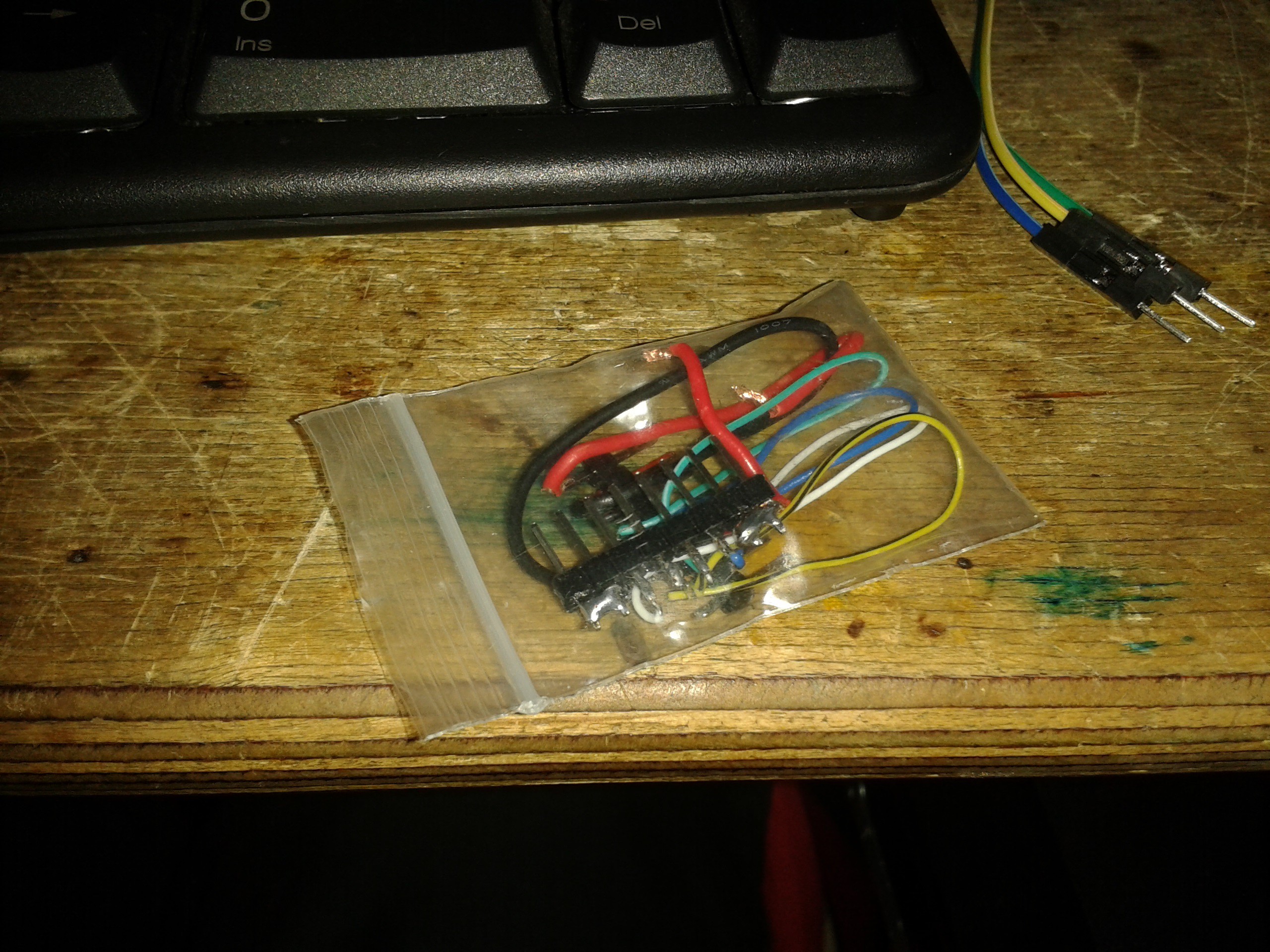 That way, I can label it something like "MSI BIOS adapter", and next time I just plug it in the same way and not worry about searching for pinouts, soldering or checking connections etc.
Some concerns:
If you're doing In-System Programming (with chip still soldered to the mainboard and leads attached to the chip), you might run into the issue that you might backpower the mainboard. In my case, the current on 3V3 line was around 300mA - and my gut feeling told me this wasn't exactly consumption of the flash chip alone, but at least it didn't hurt anything. It might be worse in other cases, in my case RPi just rebooted every time I'd connect the chip to it - so I tried not to disconnect it. In some cases though, as it is with router boards, you need to avoid backpowering. I have a SBC which will simply power up and try to read the flash as soon as 3V3 is applied, and that's not acceptable if you're trying to flash the ROM. I guess you could hold RESET signal of that SBC low though, yet to check this. I also guess old tricks with lifting pads off the board still apply, too.
Discussions
Become a Hackaday.io Member
Create an account to leave a comment. Already have an account? Log In.