 Andrew Bills
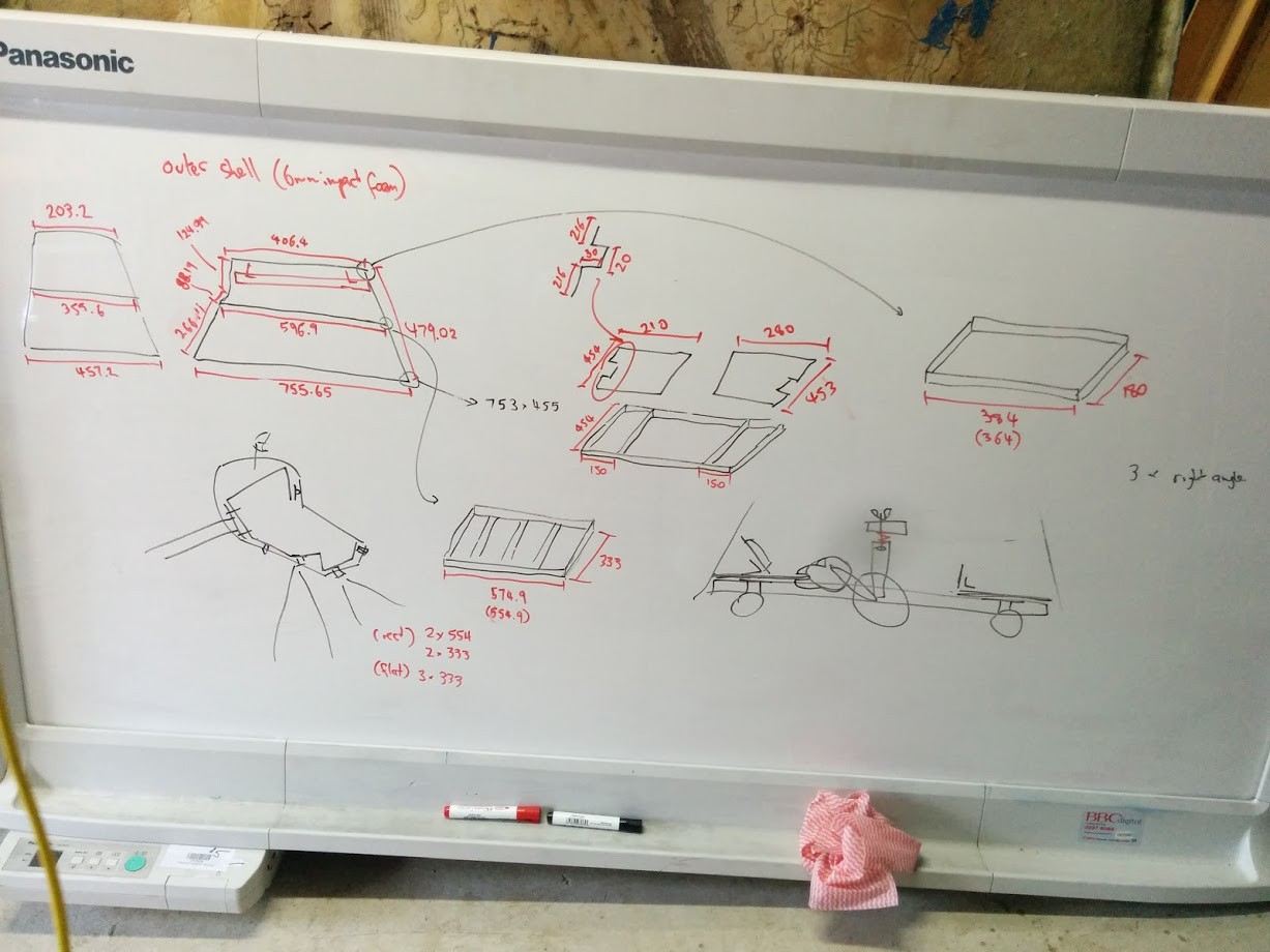
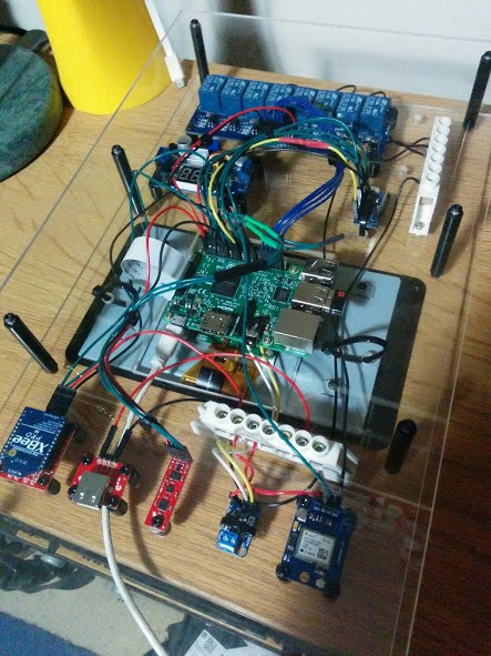
While not the most ideal diagram it does give the jist. The core is to try and do this with the one Raspberry Pi as much as possible. The arduino fio in the remote being considered separate.
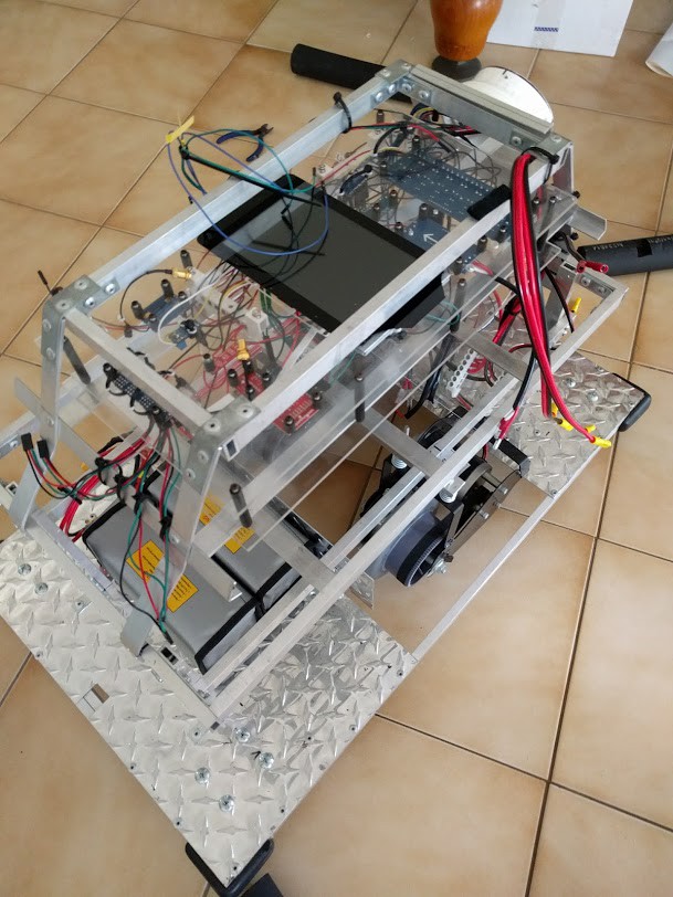
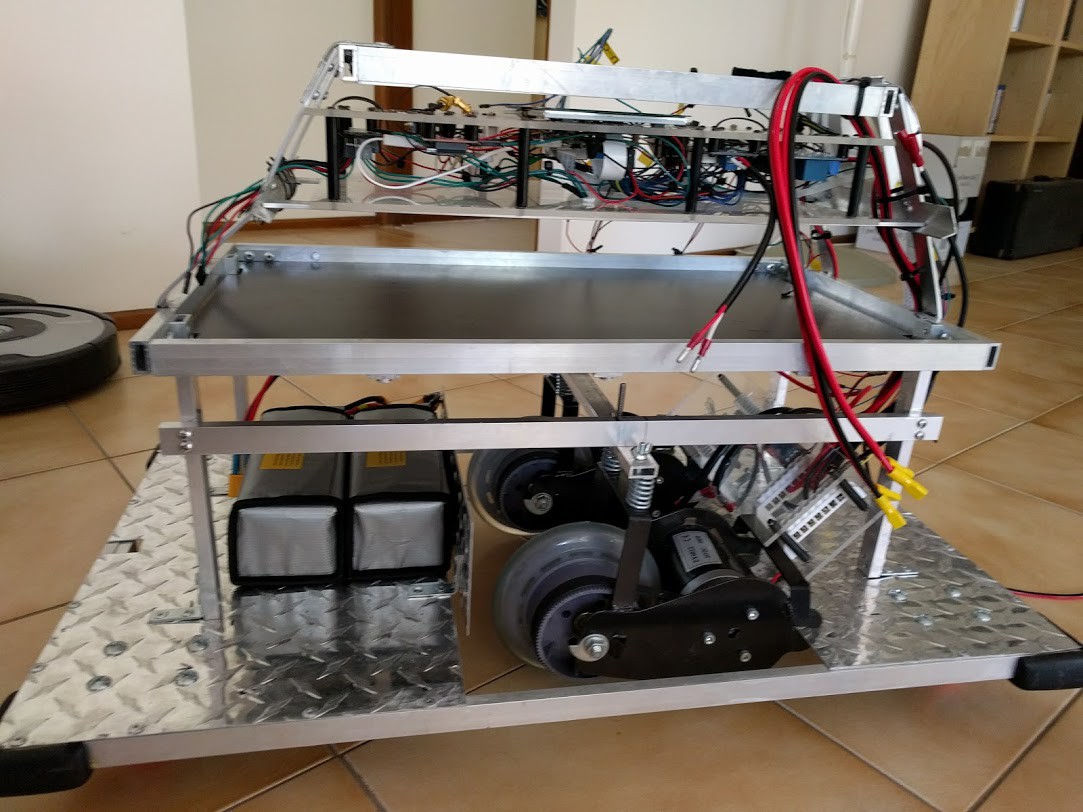
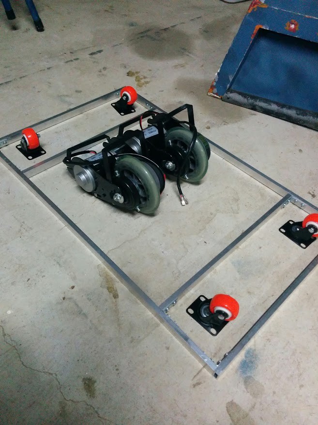
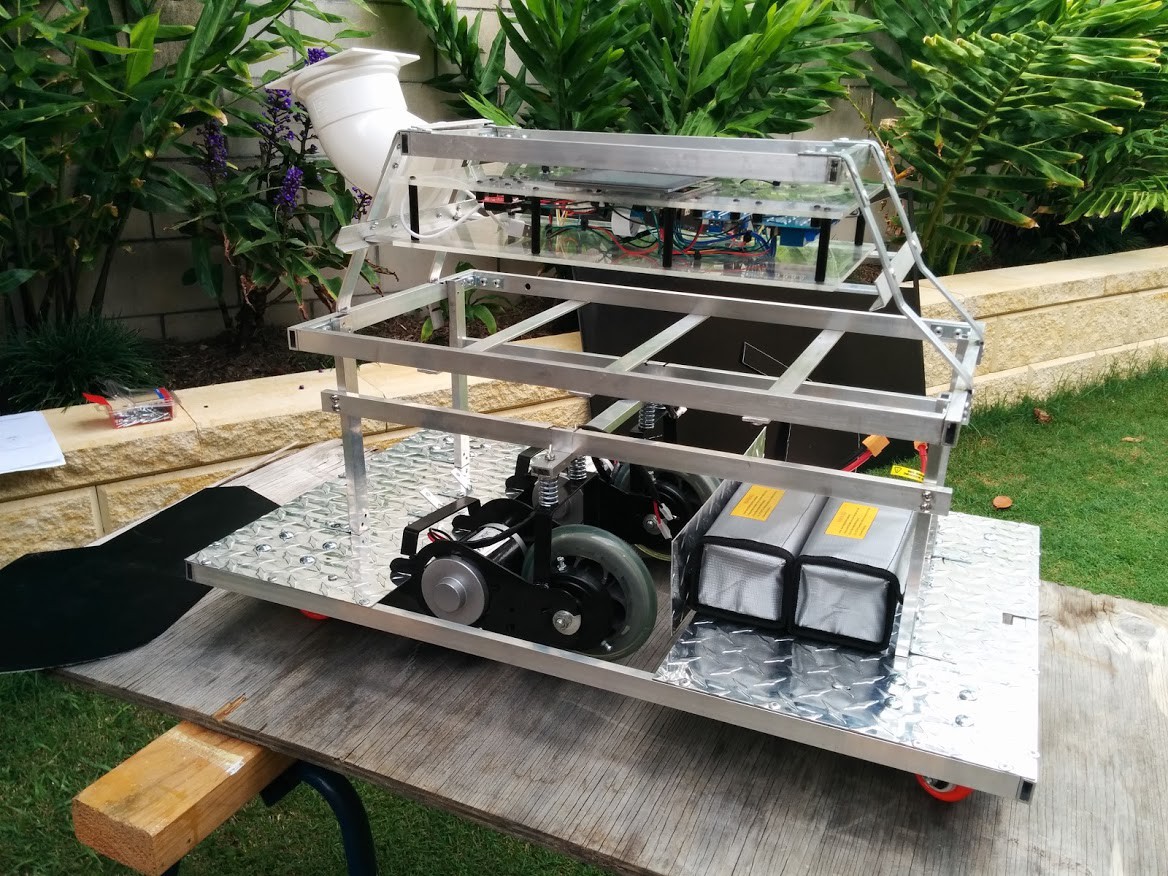
2x 6S Lipos (22.2v) are the main power to the motor controller and voltage regulated to 5v for the Pi to share the same power source. A 24v relay is used to be able to power off the motor controller while allowing the Pi to operate.
A GPS is used to the positioning but it is expected not to be able to get a signal indoors (convention halls) so where GPS isn't available the IMU will track position by offset. If a GPS signal isn't available it should be powered off for a period and retry later as not to waste power because it would be expected not to have a signal in the conditions.
Ultrasonic sensors are positioned forward, left, right and downward for collision avoidance. The downward facing one is to ensure it doesn't go down stairs. These would only be turned on when moving to save power, although tempting to have them on to avoid anyone walking into K9 when stationary. The IMU would always have power coming off the 3.3v of the Pi.
The Ultrasonic sensors use 5v to send but the return needs to be 3.3v so it would go through the logic converter before going through to the Pi GPIO. While there are sufficient relays to power off the Ultrasonics independantly it would require additional pins to power them off independantly so combining them through a single relay seems ok as they are low power too.
The XBEE would also allow for it to be powered off when not in use. It would always be required when paired with a remote but when it is not paired it isnt needed so it can be powered off with a relay also.
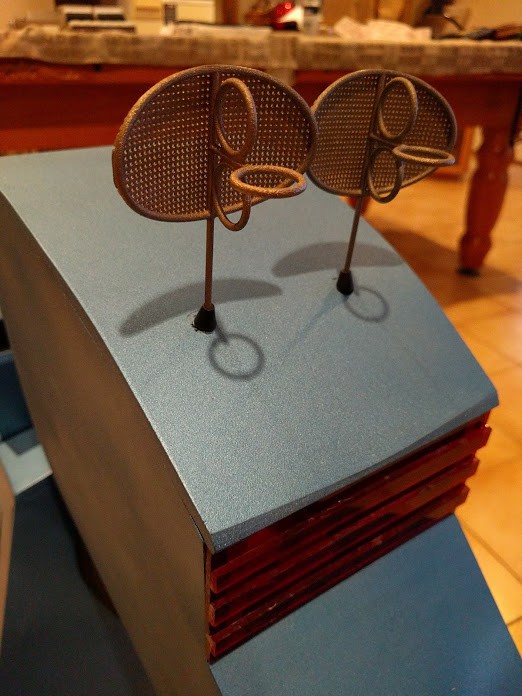
Both the XBEE and GPS could be attached to a high gain antenna as a K9 tail.

The RFID reader is a separate component that would only be powered on when stationary (so it can be paired). Pairing would be pressing something on the controller to say it's going to pair and then the device that reads the RFID for it would be paired to it. This is overkill for one robot but not if I intend to make more to use the same controller design later or have more controllers.
The controller is designed to have an induction charger in it and recharge off of K9. As induction chargers do have waste and will expend energy when not even charging a device it does only need to be powered on as required. At a later point might be able to use another RFID reader near the induction charger to only turn on when the device is there, but I also want to use it with my phone so may be a switch or maybe via the RPi touchscreen which is also being installed.
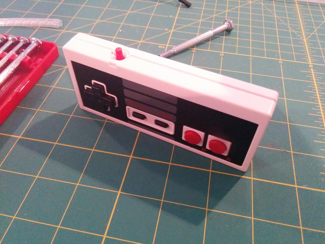
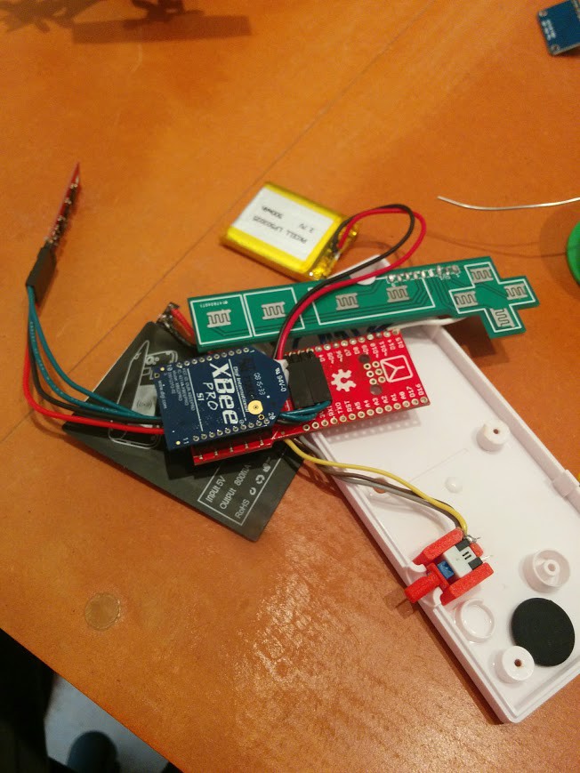
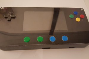
The controller is going to be inserted into a USB NES controller shell and use a Ardiuno Fio v3 which has built in XBEE socket. The case will need some adjustments but there should be enough space for mounting the board + 500mah battery + tiny induction charger + buttons + on/off push switch + 9DOF.
 (*note this is not the exact same board as I have but I have drawn it to the correct pins for my usage)
The controller will also have a small glass RFID tag in the case so when the user presses 'select' on the controller K9 will turn on the RFID reader to scan/pair. When a controller is paired it will start sending it's accelerometer data to K9 which will know where the controller is in relation as from the point of reference of the scanner + movements. This will allow K9 to have a 'follow me' mode while the controller is paired.
Secondary to this the A/B/Start/Select/Up/Down/Left/Right buttons will also be hooked up to allow for (in addition to pairing & starting follow me) direct drive remote controller. The intention is not to have K9 as a remote control prop but it will be helpful initially no doubt.
The induction charger in the controller will be wired to (bypassing) the usb charge connectors on the Fio with the existing lipo heading on the board removed due to space/height issues. This will allow the controller to be charged wireless...
Read more »


 Lumor
Lumor
 Jorj Bauer
 Retroplayer
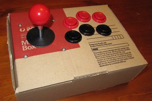
 Robbo
Robbo
I am still a little on the fence about battery choices, I think 2x 22.2v 6s 16Ah batteries will be perfect especially if i connect them in parallel so i can change them over without losing power (if I need to) but Lipo arent really as cool. Wish there was a small hydrogen cell/lipo hybrid option that can give me the 24v too.