 Andrew Bills
So, I'm getting a bit concerned about having this together in time for a con that is in 2 weeks time (by bit I mean VERY) I was relying on someone else for the shell that I need around the frame and they have so far let me down. It is looking pretty doubtful to get it done in the short term and if it is done it might only do the most basic remote control features.
Speaking of the remote control, I made some effort to try and polish that off yesterday/today but can only get so far due to the fact that the induction charger I need was faulty and I've expressed it off to get a replacement. Soon as that arrives I can solder it back in, connect the plunger switch (which I had 3D printed and the files are here) & glue it down.
The controller is very tight (as expected) so there is a little jiggery pokery to get all the cables in the shell, but it is doable. I will need to add some foam packers when the switch and charger are in too to make sure stuff doesn't move about.
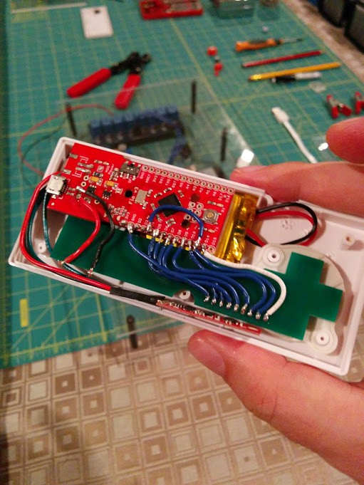
You will have to forgive my horrible soldering ability. I had originally intended to use headers on the wires but the space was too small so I had to remove it (poorly) and go direct. The button pad board is per the Gerber that is also in this project that I got made as a prototype (min order of 5, so I have spares). One pin is for grounding and the rest are for input. I had some problems with the FIO v3 that one of the digital pins (14) was actually a different number (17) and try as I could I couldn't get anything out of pin 11 hence the one cable that just jumps over to pin 4.
Fun thing if you do this, it does vary from the schematic I put up originally for the controller.... I have the 8 buttons on digital pins 4-10 + 17 all of which are initialised as HIGH to use the onboard resistor so I don't get button bounce during digitalRead (can happen). My custom part 9th pin I couldnt get right with the onboard pins (maybe due to the faulty pin I was trying to do everything with until I figured that out) so its just connected to ground given the other pins are all set HIGH.
Code wise the thing outputs to Serial1 (xbee socket) and just pumps out a string of current values of the controller on a 50ms loop. I did slow that down at one point but felt it a bit sluggish when coupled with the logic.
Long story short for the code it outputs:
RFID Tag (inserted inside the case), 8 button settings of on or off, xyz for accelerometer, xyz for the gyroscope and xyz for the magnetometer. It also outputs the pitch, yaw and roll per the Madgwick filter but ill come back to that. All comma separated.
So I elected not to made corrections to the calibration of the 9DOF sensor stick I am using because I read bad calibration can be worse then ok factor calibration. However the Accelerometer part has a self diagnostic I could call on at start-up so I did that. The magnetometer & gyro didn't really have the same options and really depended on more offsets being used to set them up.
What I have included though is on top of the standard calibration to use the Madgwick filtering for AHRS on the 9DOF in the controller. Considering I may want to use the controller as a short term follow me treating it like a drone IMU seemed like a good idea (even if I don't get to use it right now). Basically it takes the accel, gyro and magno data and constructs it into the pitch, yaw and roll mentioned earlier. But the added bonus is when it does that it will do some sampling filtering to help with gyro drift (because all gyro's drift, its what they do apparently as they warm up... supposedly they will settle down but yeah).
Anyway as soon as I get the induction charger replacement Ill connect that up, solder in the external switch & I will be good to close up the controller. Earlier versions of the Arduino Fio allowed for remote bootloading with a little soldering but I am led to believe that isn't an option on the version I have so I wasn't game to further butcher the board with terrible soldering.
Couple of screws and a little foam packing and it will be closed up not to be opened again.... but definitely some lessons learnt if I make another controller as to how to save a bit more space.
As it is Zombie Jesus weekend (Easter) and I wont get those components tomorrow I can go back to trying to get the RPi3 working the way it needs to out of the box. The RPi3 which is a better choice for performance unfortunately doesnt have the serial working the same way as a RPi2 due to the inclusion of BTE. Ive followed a few guides with no success so Im going to start over again with the most basic one I have access to and hopefully I can move past solving problems I shouldn't have to.... (else Ill have to revert back to the RPi2).
For anyone's amusement Im also including the prop diagram that most people work to. I was trying to find someone with CAD (and the ability to use it) to convert it into some slices I could get CNC'd into some impact foam panels I found but no luck yet.
Discussions
Become a Hackaday.io Member
Create an account to leave a comment. Already have an account? Log In.
Whatever you linked in this article, it doesn't show -- I only see a "no entry" road sign icon.
Are you sure? yes | no
Was just a picture (that was showing up for me). I removed it and readded it, maybe it shows for you now?
Are you sure? yes | no
It works now, thanks!
Are you sure? yes | no