 Andrew Bills
So I spent some time on wiring yesterday to get most of the main body wired correctly... as much as I could without the correct 5v voltage regulator (ordered a replacement, should of been here on Friday hopefully Monday). Much like the description it isn't as messy as it looks.... I shorted up a couple of wires but the bulk of 'mess' is just the 5v to 3.3v logic converter needed for the return signal from the ultrasonics.
While I was fiddling I also rewired the serial cables (as the ones I made previously were a little.... iffy it seemed and required some wiggling) and made a 1 to 2 connector for the I2C bus so that I could connect in the microphone later using a ADC converter (which I might also do but it's non-critical). I also decided to use some of the white plastic power bus' you can see in the picture for power distribution at the top... then had to order more with expensive express postage for the bottom seeing how I only had the one set.
I also switched out the relay that wasnt working with a new replacement. The old one wasn't working partially because I didnt understand what it was doing properly but mostly because all the connectors were rusted to buggery. The new one works great but I did have to re-drill some of the mounts because they were different sizes & as a result only 2 of the mounts are screwed into the board due to the holes on one side being too close to the relays to screw down without damaging stuff.
Not a complete waste as I had to mount the power bus' anyway + I was able to create some extra holes for zip tie loops that I might use as cable guides (you can see 2 guides on each side of the Pi for example).
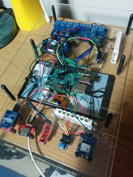
I also connected up the external amp so I can plug in the 3w speaker that will be in the head. How? I wired directly to the soldering points just like you would if you were building a Pocket PiGrrl with a PiZero (https://learn.adafruit.com/pocket-pigrrl/pi-audio).
So seeing how I didn't have a frame or ability to power it up properly yet I connected in the 5v usb I have been using to check individual components and installed some stuff. Specifically - Kivy (touchscreen stuff) and OpenCV on a virtual (recognition stuff with the camera).
If you are interested in those here is more or less the guides I used.
- Kivy https://github.com/mrichardson23/rpi-kivy-screen
- OpenCV http://www.pyimagesearch.com/2015/10/26/how-to-install-opencv-3-on-raspbian-jessie/ (inside a virtual, may decide to move everything over to the virtual... havent decided)
- I2C tools so I can check the 9DOF was still working with the wiring https://learn.sparkfun.com/tutorials/raspberry-pi-spi-and-i2c-tutorial (I probably will pick-up a ADS1115 next week to connect the microphone for voice recognition later)
- Logitech Unifying Receiver (as I got a super cheap Logitech K400 KB from a store that was closing down and figured might as well) https://community.linuxmint.com/tutorial/view/1459 FYI if you do this you may not need all the steps. I couldn't get it to detect but it was just working
What's next? I might make a few modifications to the controller code so when you turn it on it doesnt automatically send all the sensor data. Partially because I may or may not get a replacement induction receiver that will fit next week so may want to save power first time out of the gate & partially because the way the Arduino Fio v3 are wired when I charge it it will just turn on so less power it consumer when just accidentally turned on the better for that.
The Panels for K9 FINALLY went to get CNC'd yesterday. They are going to be 6mm high density impact foam panels. Long story short, should be able to take a hit & not break + fairly light comparably to my other options. Also perfectly OK for signal like RFID which is through the chassis. If you decide to do this remember when using the prop plans that some panel heights are on an angle so you have to use some maths to figure out the angle and actual lengths of the leaning parts.
Because the panels went off yesterday and I do want at least something that looks right (even if it doesn't do anything) by next weekend for an event, will be assembling a frame tomorrow as who did the measurements for the panels assures me they have the dimensions correct for us to do that. Hopefully log/pictures tomorrow/Monday of a skeleton, mostly assembled K9.
Discussions
Become a Hackaday.io Member
Create an account to leave a comment. Already have an account? Log In.