 Andrew Bills
I was planning to give an update last week but my kitty cat died and all motivation has drained out of me. Yes I realise how mad scientist it looks to lose a pet & be building a robot one but let's not think about either of those things... so 2 updates. Button pad and how I'm going with the outer shell.
Button Pad
So as mentioned I was doing the button pad and it was raining last time. It fined up enough to be able to bend the plastics I was going to use for inside the shell.
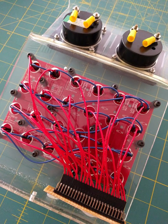
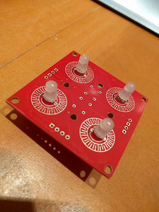
So the short version of the above is that I bent some perspex with a heat gun into the shape I waned. I have a selection of button pads from Littlebird/Sparkfun with a matching button pad shield underneath. To do this with only the single Raspberry Pi the LEDs I mounted aren't RGB but NeoPixels that I can address from a single pin in serial (as power hungry as they are).
What this meant was the mounting boards were for RGB LEDs and wired for those sort of pins. So what I did wasI cut the circuits on the board so the LEDs can just use it for mounting (which works better with the buttons. This means the buttons don't work but the buttons aren't suppose to, they are a decoy for anyone who feels the need to poke or touch K9 (which someone always does and breaks something).
After wiring up all the pins and power for them all I did a cardboard version of the box and then used that as a template to cut a box from the same high impact/density foam that K9's body will be made from.
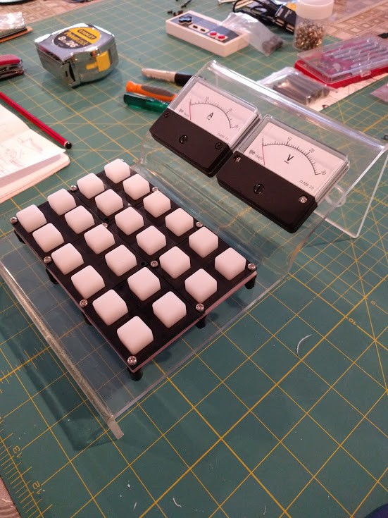
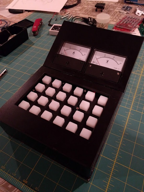
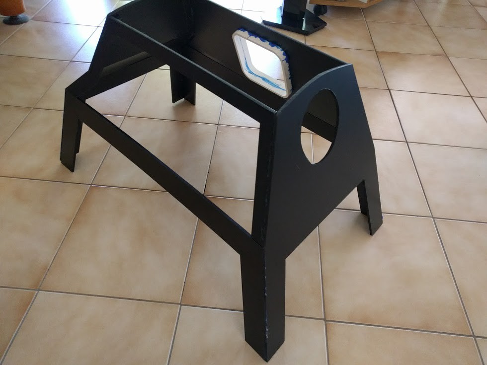
Ok so the control box has some problems. The buttons are sunken and hidden which is entirely not the point of them and I think the gauges sit up way too high but probably will have to wait to see how low this all is in the body before I can modify them. The box here is intended to be a lift out (maybe motor out) cover for the touchscreen in K9. So you lift this out and can get to the touchscreen for more specific controls.
The gauges here are not per the props for K9 and I don't care because they are more functional. The Voltage and Amp meters are hooked into the 24v power distribution lower down in K9 to give some idea of usage. In this version as you can see I have angled them so they can be seen quite easily but again, they might sit up too high now and will have to decide if I break my plastic frame under to lower them.
SomeBODY to Love
The second update is about the body which has progressed some. If you have read all the logs you know that I was not happy with the measurements for the body being done incorrectly and potentially wasting a lot of money but I am trying to use them first before resorting to more spending. The short of it is when laying out the measurements who did it did not take into account the angle of any slopes. Basically that thing in school about hypotenuse? They didn't do that.
So what this means for the body is, instead of it nicely sitting over the top of the frame and hiding it it wasn't going to be long/wide enough. Given that to be a fact I had to decide whether I lay the pieces on top of each other to give me a couple extra mills length or width. I have elected for length. (insert that's what she said joke here.
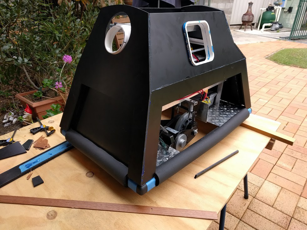
The body is high impact foam which can be cut with a VERY sharp knife and some effort so it was not quick or easy going. I also had to reuse some scraps because along with the measurements not being done correctly not all the pieces were sent to be CNC machine cut. The high density foam however is plastic in base so it could be stuck together with blue plumbers glue.
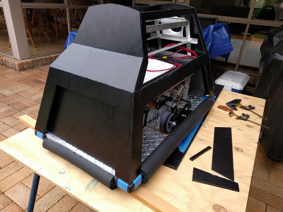
A few pieces needed bracing pieces added to give them more to stick to but the end result is per what you see above. To attach/detach it is a little bit of a trick with the head and neck needing to be removed first if you want to completely strip down. The body is pretty tight with some packers added to make it sit exactly without and twist to it.
Because the measurements I was given were so wrong the body now sits onto of the frame instead of hiding it. To help I purchased 4 rubber table corner things for each corner, seeing how if it did take out someones leg the body wouldn't cover the sharp metal anymore. I also included the 4 foam protectors around the edges, while it was in the plans I was hoping not to have them because I didn't like the look of them. Now I am using them to cover more of the metal body due to the above reasons.
The body isn't complete with the head still to go and the door on the battery side to be made (with some fancy hinges Ill post about next time hopefully) + the head which has it's own challenges with the more sturdy material. But hopefully soon I can actually have all the wiring inside and hook it up to start messing with the parts that actually make it do things.
Discussions
Become a Hackaday.io Member
Create an account to leave a comment. Already have an account? Log In.