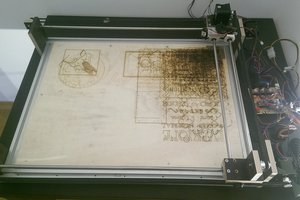
Presented printer imports the PCB layout as a bit-map image and prints it out similar to a paper laser printer. It covers whole surface of the PCB line by line turning the laser on and off to recreate the image pattern. To achieve a reasonable resolution and short printing time, each of the laser passes over the PCB has to be relatively fast. This requires short switching time of the laser and high bit rate of information.
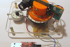
Hardware design of the printer is very simple (see pictures). One fast rotational axis with laser at the end of the arm and second slow precise linear axis to progress over a PCB, line by line. Both axis are power by stepper motors. Electronic side of the project was design around Raspberry Pi as a main processing unit and few axillary circuits. Pi reads a PCB layout as a bit-map image (easily exportable from most of PCB design programs). After a few kinematic calculations, Pi is able to create the signal pattern for the laser. This patter is then transmitted over the RPi’s SPI. Each SPI data packet controls one laser pass over the PCB. Output data goes directly to the laser driver. In the driver, the SPI packet is decoded into bit stream by single D-type flip-flop. The signal from the flip-flop is then applied to the voltage to current amplifier which then drives a laser. Laser diode used in this printer is standard Blu-Ray recording diode (Sony SLD3234 125mW 405nm). The SPI’s clock signal is also send to the motor controller which tries to match it with the motor position. The motor controller is made out of an ATmega328 and two DRV8825 stepper motor drivers. Step resolution of the arm motor (1.8deg/step) is not enough for printing, but assuming a constant speed, its position is interpolated in time.
At the current state of development the printer achieves a desired resolution but printout has a small insignificant wave in it. Main down side of the printer is its lacks in speed. It takes around 10 minutes for it to progress 1cm over the PCB, which results in half an hour printing time even for a small circuits. Main factor which stops the printer from achieving higher speeds is the inertia of the arm. The stepper motor has to accelerate, maintain constant speed over a PCB and then decelerate the arm in the shortest possible time. At best it still takes around half a second to do it. The best solution to this problem is to copy the design from the paper laser printers. In such printers the laser is stationary and its beam is swept across a paper by rotating with constant speed mirror. Reproducing this arrangement will be probably the next step in the development.


 iliasam
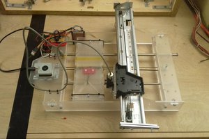
 JLAM
JLAM
Look this project:
http://radiokot.ru/forum/viewtopic.php?f=8&t=119089