 Jim Shealy
I went over some of the reasons I really like the PSOC architecture as a platform in the "Intro to PSOC" update. But I want to get into the actual issues and things to know for the new user to prevent wasting tremendous amounts of time.
1- Microcontrollers
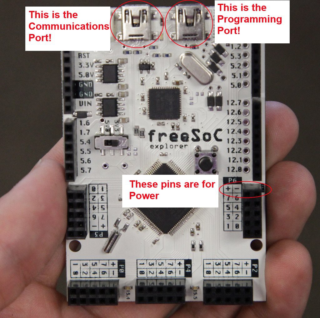
Let's start with micro controller hardware differences. If you've only ever used the Arduino, it turns out the programming/debug port is not the same as the communications port! I spent countless hours trying to figure out why the serial port wasn't enumerating (read 8+ hours). It turns out that it's normal (and apparently obvious) that many micro controllers have more than one port, and programming/debugging is handled separately. I couldn't find any answers online, well because no one had the same problem, there wasn't one! upon plugging my usb cord into the other port I applied my head directly to the table because suddenly the serial port worked. Oh, and just remember to check if your pins are not actually micro controller pins, but power pins. It'll save you some rewiring.
2- Floating Pins
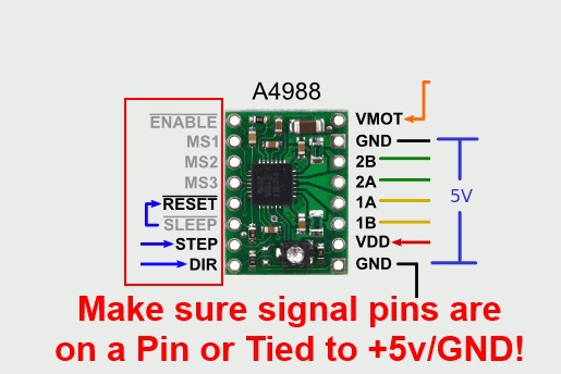
I had some interesting gremlins in the wires when I started coding for the stepper motor controllers. As it turns out, if your reset, sleep, or enable pins aren't tied to a polarity, you'll have very flaky control of the stepper motors! But, that's not limited to just those, ALL signal pins must be attached to a polarity or enabled pin to prevent floating. While it's neat to be able to hold your hand near the wires and have the robot arm start moving on its own, it's extremely frustrating to figure out!
Additionally, make sure the Microcontroller pins that the signal pins are connected to are actually defined by the PSOC controller. All of this is done through the PSOC Creator software as shown below:
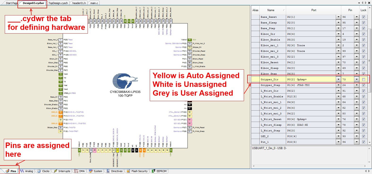
If you have yellow auto assigned pins, you should make sure they're actually the pin you want! On the FREESOC the pins have silk screened labeling that calls out the port (P4[7], etc.) instead of the pin number. While all the breakout/development boards may not do this, it's not a bad thing to keep in mind. Part of my floating pin issues were due to pins being plugged into micro controller pins that weren't defined, and thus didn't have a polarity!
3- FPGA Hardware (or UDB components) Must be Started
This is something that took me ages to figure out, but components must be started before they do anything! Many component data sheets say this, but it's not always explicitly called out. That's a major difference you'll see with PSOC and a CPU only architecture like arduino. Not only that, but there are ~4 commands used to start components.
componentName_Start()
componentName_Begin()
componentName_Init()
componentName_Enable()
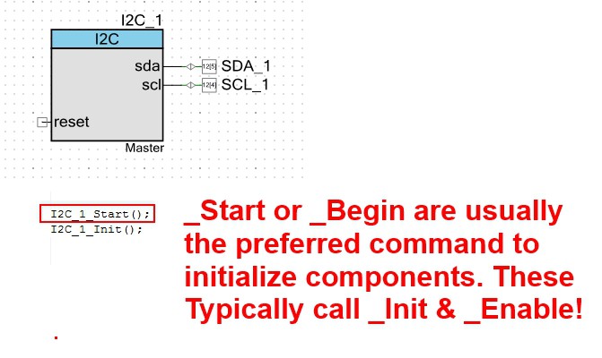
Some components need to be initialized before they can be enabled. Others only need to be enabled. The key to this is is that if there is a _Start() or a _Begin() command, use these as they'll take care of initializing and enabling in the correct order. Because Cypress' PSOC Creator auto fills, just try one of these two commands first before worrying if there is a specific initialization order.
While PSOC creator auto-fills, make sure you've built your project BEFORE trying to code! The build command creates the code handles you will use, and they'll be unavailable if you didn't build after inserting a hardware component.
4- Clocks
PSOC allows for tremendous flexibility and ease of setting clocks. Unfortunately that ease can make communications protocols break down because you messed with the wrong one (IE the USB clock!). Let's dig into that a little deeper:
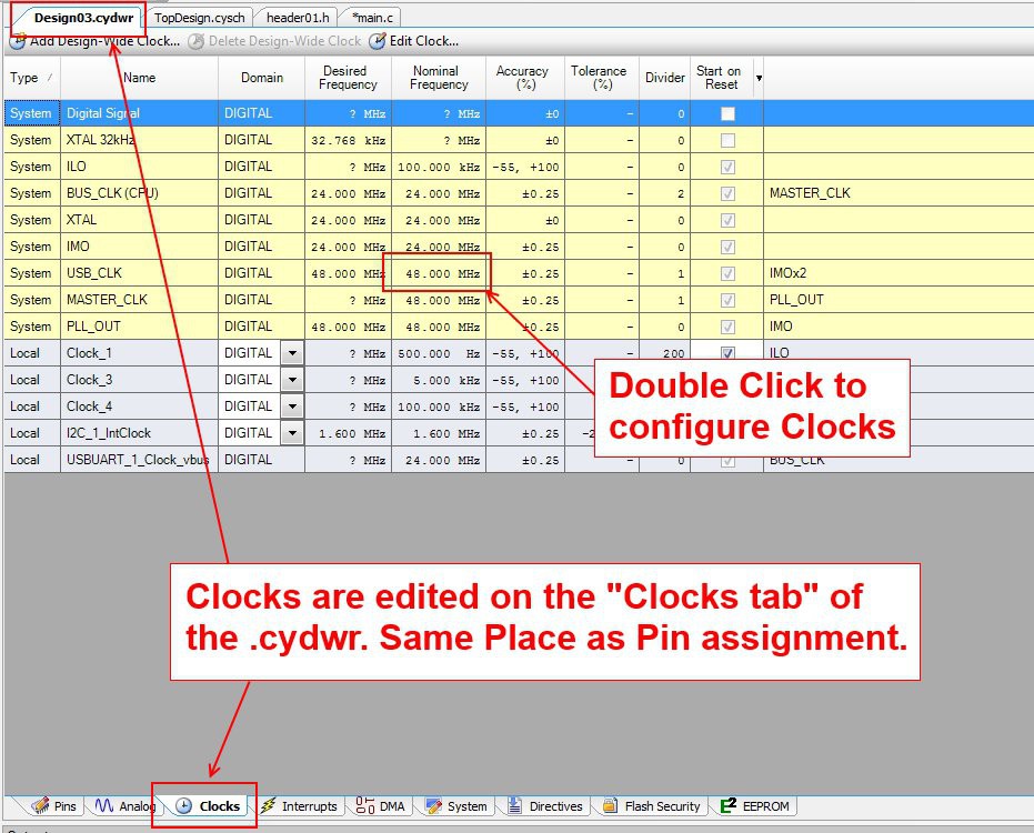
By double clicking the clock frequency box, you'll be taken to another page with the clocks, showing how they're all interdependent or dependent depending on how you set them. The lines show what connects to what, and which clocks you can base other ones off of.
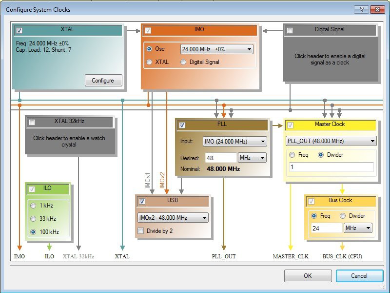
I won't pretend to understand what all the clocks actually mean, but the important thing is this, The faster the bus clock, the faster your CPU.
BUT, you wanted to use USB right? USB should be 48.000 MHz with a tight tolerance, but the CPU can be run to a maximum of 67MHz. These aren't multiples, and you'll get low tolerances with your CPU clock if you try to do a frequency that's not a multiple. This is the underlying issue that while PSOC has great flexibility with clocks, all of your hardware clocks will be based off of something you set here with some sort of frequency divider. You'll have to find a configuration that is divisible into the frequencies that you need for your components, while having the fastest clock speed available for your CPU to aid in processing.
I would suggest spending some time familiarizing yourself with the diagram, and notice that the arrows point to what the clock output is being fed into. In order to keep the USB at a tight tolerance I've set the XTAL to 24Mhz, which feeds the IMO to a tight tolerance. The USB can then be made 2x the IMO to be the desired 48Mhz. the PLL also feeds off the XTAL or IMO its output is set to double the input to also achieve 48MHz. This then directly feeds the master clock and the bus clock.
I also believe the I2C that I use for the Wii Nunchuck is based off the ILO which I've set to 100kHz for "Fast Mode". It also makes for very easy math and I'd recommend it!
If someone has suggestions for a different configuration of these to achieve a faster output, I'd love to hear it! This is what I've found so far to be a stable configuration for all the components I'm using, and I hope it provides a decent fallback if you start getting clock errors. You might have a heck of a time trying to figure out why your component isn't working when it turns out to be a clock failed to initialize because you didn't obey its operating perimeters.
Discussions
Become a Hackaday.io Member
Create an account to leave a comment. Already have an account? Log In.