 Russell Kramer
I'm assuming everyone knows how a light gun system works. That is not how this light gun system works. It works by generating two ramping voltages that follow the raster beam horizontally and vertically, then using two sample-and-hold circuits to store the ramping voltages when the zapper detects the raster beam. This produces two analog voltages that indicate the position of the zapper's aim on the monitor.
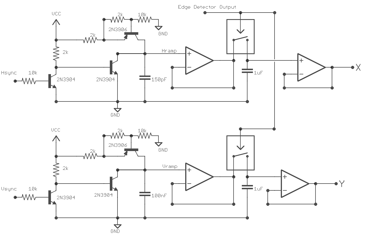
The ramp circuits use a 2N3904 trigger and a 2N3906 for current regulation. The current flowing to the ramp capacitors needs to be regulated to make the voltage across them rise linearly instead of the curved natural logarithm they normally exhibit.
The sample-and-hold is produced with another 74HC4066 quad analog switch and a TLC274 op-amp. I was originally using an LM324 op-amp, but I found it did a really bad job following the horizontal ramp. LM324 is an audio op-amp and the horizontal ramp frequency is much higher than human hearing.
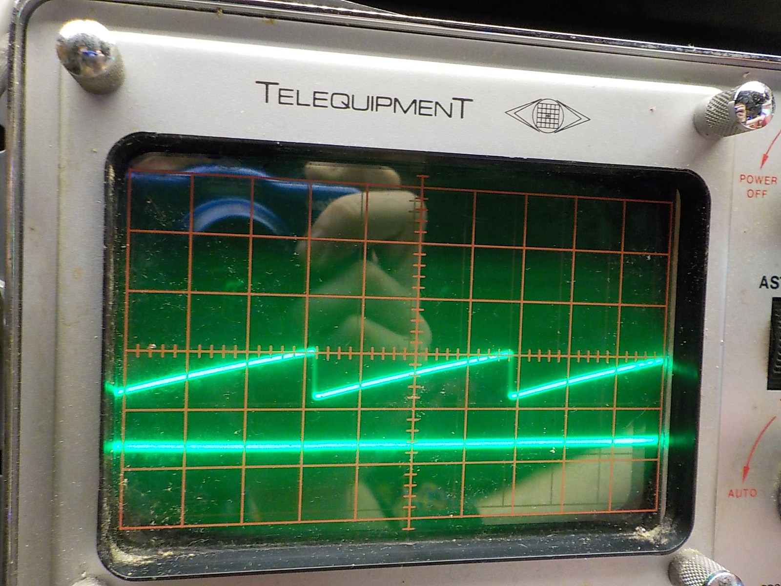
scope showing Horizontal ramp. 5v between the scales..
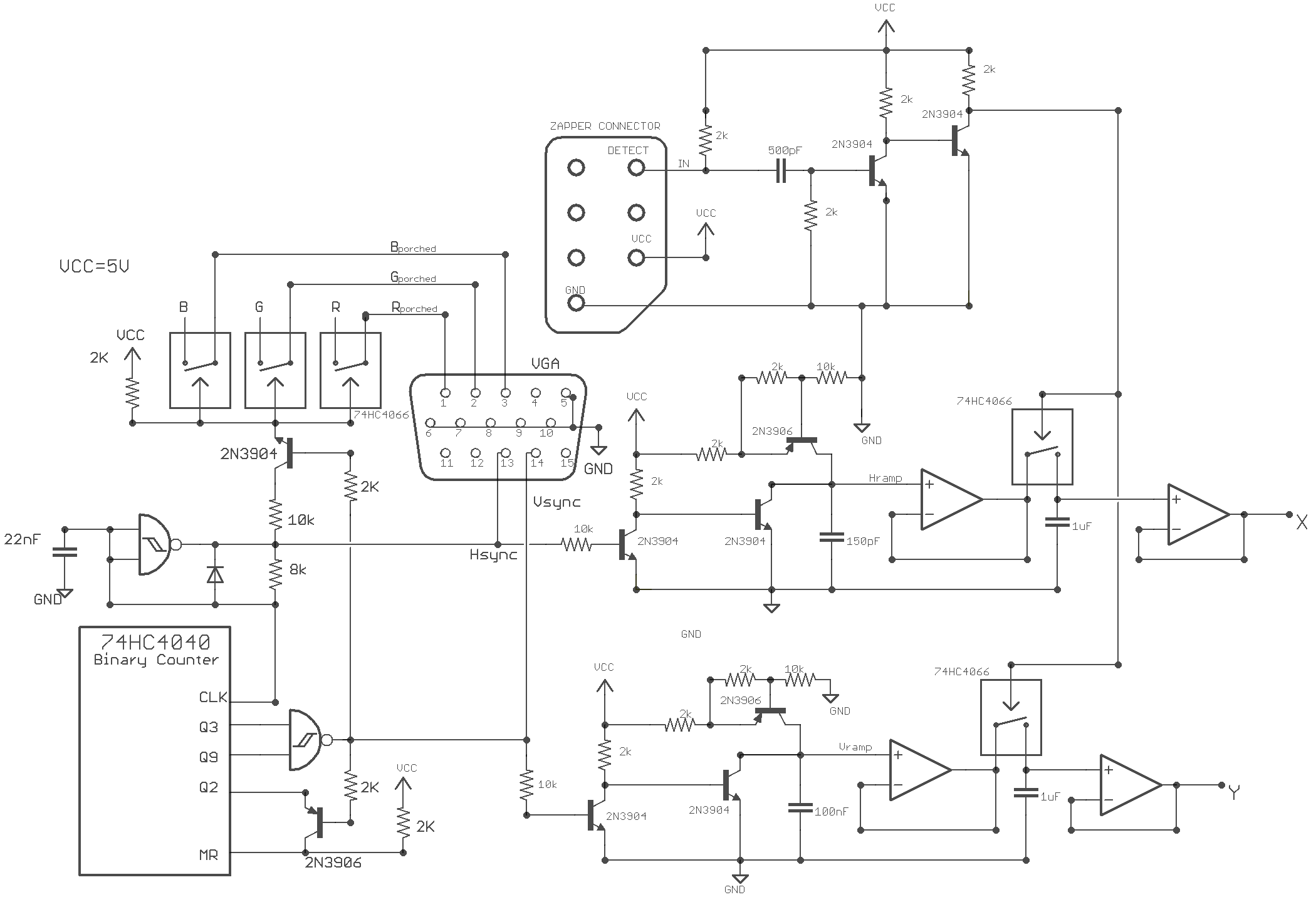
Circuit showing the VGA signal generation, zapper edge trigger, ramp generators, and sample-and-hold.
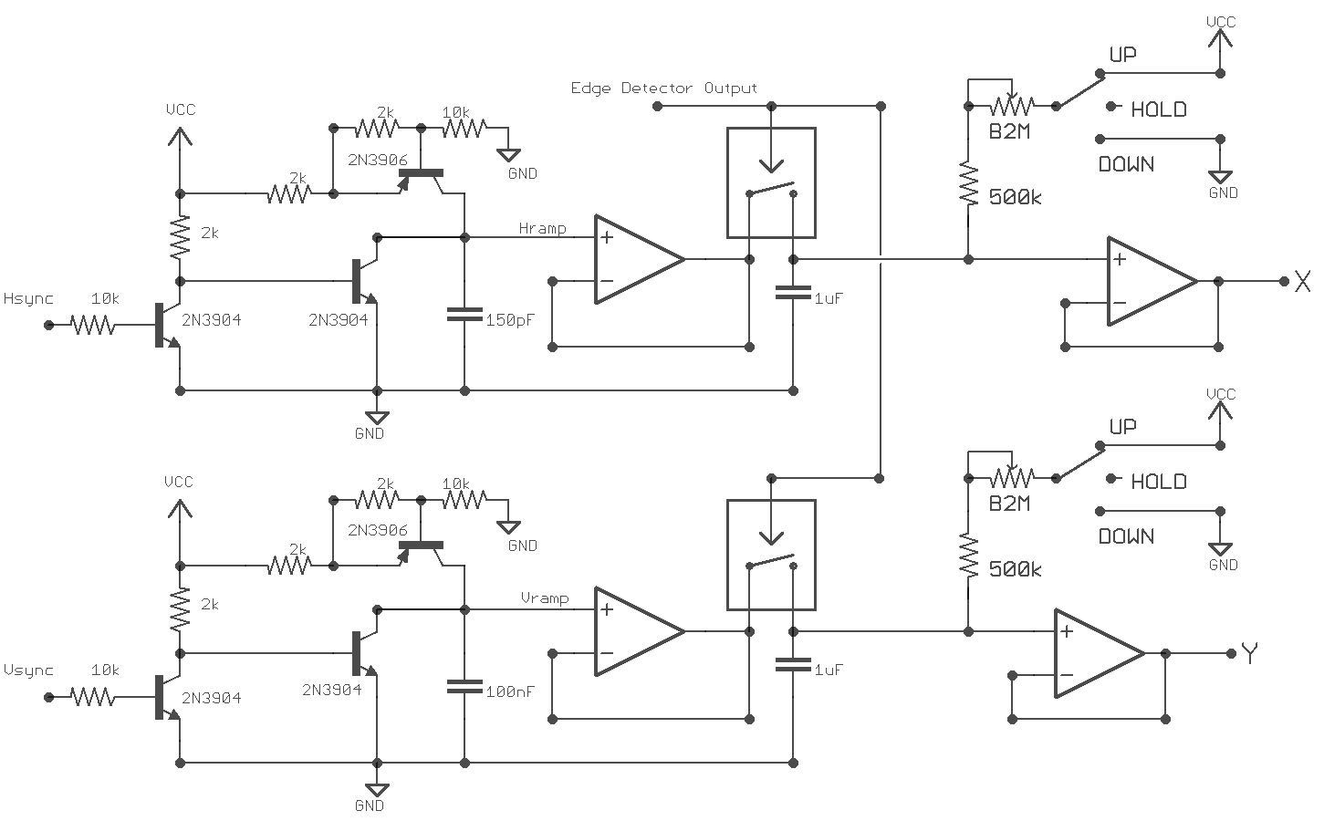
Next I added some additional controls to the sample-and-hold circuits. When the zapper is pointed at a dark area of the monitor or away from the monitor the holding voltage of each axis can remain unchanged, climb, or fall. This is selectable through a sp3t switch and the speed of the rise or fall is controlled with a potentiometer.
A higher control voltage results in a higher frequency from the VCO, which results in changes to the video output. The sample-and-hold output responds to a dark area of the screen differently than an illuminated one , so now there's a feedback loop that creates some very interesting sounds and video patterns.
Discussions
Become a Hackaday.io Member
Create an account to leave a comment. Already have an account? Log In.
I need to look at the datasheet, never used them. Very cool circuit.
Are you sure? yes | no
Nice linear ramp, I guess you're charging capacitance with constant current generated by the BJT. Is that a relay at the output?
Are you sure? yes | no
Those are 74HC4066 solid state switches not relays.
Are you sure? yes | no