0%
0%
Nerf Target Board
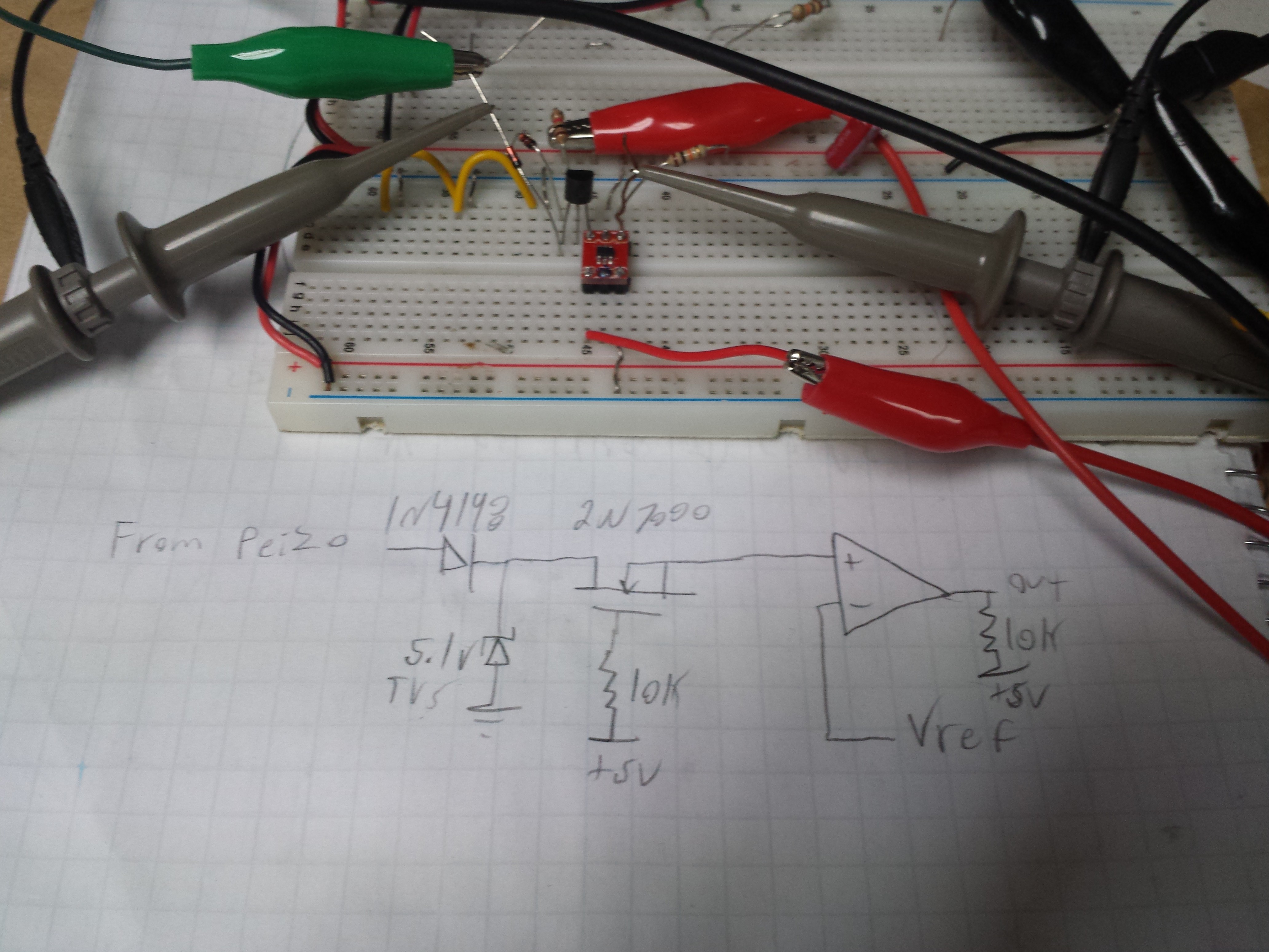
This is a Nerf target similar to a dart board witch will have a built in scoring system
 Spencer
Become a Hackaday.io member
Already have an account? Log in.
Just one more thing
To make the experience fit your profile, pick a username and tell us what interests you.
Pick an awesome username
hackaday.io/
Your profile's URL: hackaday.io/username. Max 25 alphanumeric characters.
Pick a few interests
Projects that share your interests
People that share your interests


 Niel Malan
 AKA
AKA
 Tom Meehan