 Dan Julio
One of the configurations I tested during debugging of the original prototype of the board was a Western Digital hard drive connected to the board along with a WiFi dongle and keyboard/mouse powered by a USB charger. The average current consumption (even when the battery was fully charged and at its highest output voltage) was above the maximum 750 mA that the charging circuit could provide which meant that the battery was slowly discharged. So there was no way to use the Pi Platter as a battery backed file server (or other HDD-based application). I thought briefly about trying to find a different charger (750 mA is near the bq24210's upper limit). The problem is that to support our maximum load of 2 A it'd have to be at least a 2 A charger which would increase cost as well as possibly limit the battery selection since 2 A could be too much for smaller batteries. So I decided to add a bypass circuit that would power the system directly from the USB charger and from the battery through the boost converter for solar applications or when the USB power failed. This meant a couple of new control signals to the PMIC that was currently out of spare signals. One thing I had been contemplating already was making one of the USB ports "always powered" instead of switched to prevent a case where the user could make it not possible to access their Pi to make change. This freed up one signal. I decided to remove the Power Good status signal from the bq24210 for the other since it didn't seem all that helpful.
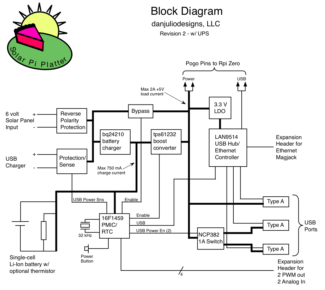
The critical timing for the UPS functionality is switching from a failing USB Charger voltage to power from the Boost Converter without the +5V rail falling below 4.5 volts. There are 3 parts to the timing, a falling USB voltage to some threshold that indicates it's no longer good, the time for the micro-controller to detect and act on that signal and the time for the boost converter to start up. Switching from battery power to USB power isn't as critical because we can leave the boost converter running for a tiny bit while validating the USB voltage and switching the bypass back on. The USB Charger voltage is fed through a resistor divider into a comparator on the micro. The output of that is routed as the highest priority interrupt so the boost converter can be switched on by an ISR and then power-fail validation, state management, etc can be done in the main code. Voltage falling below around 4.7 volts to boost converter enable is less than a micro-second. It then takes a few milliseconds for the boost converter to start up which can be covered by bulk capacitance on the board.
The bypass is comprised of two back-to-back P-channel MOSFETs to prevent current from flowing in the wrong direction depending on the various use cases (USB power but no system power, USB power and system power, no USB power but system power). I ended up having to add a N-channel MOSFET switch for gate control since the micro may be running at a lower voltage and can't keep the P-channel transistors entirely off (Gate = high-side voltage for off).
I think I will add a green/red LED to the next revision of the board because one thing that became obvious when testing the original prototypes is that we didn't always know when power was on or off (the green LED on the Pi is extinguished when the system shuts down).
Here's a video where I not only forgot which was the P-channel FET but that I was using 2 of them (in my defense it was at the end of a long, long day shooting video for the kickstarter campaign and I wanted to go home).
I've done quite a bit of testing using both a dynamic load (Arachnid Labs ReLoad Pro) and real systems including with both the WD314 HDD and a 1 TB HDD. Interestingly the small voltage drop when the USB power is disconnected caused the 1 TB HDD to retract it's heads. We heard a click whenever we disconnected USB power but the system kept working. I guess it saw the slight voltage dip as an impending power fail as well.
Discussions
Become a Hackaday.io Member
Create an account to leave a comment. Already have an account? Log In.