 Russell Kramer
This has been completely stand alone video synthesiser up to now, but I've had a lot of input encouraging me to use the glove system to add distortion effects to an external video signal.
I went to an E-waste recycling center looking for things that make video that wouldn't be suspicious in 1987. I came back with a T5200 and VCR. My goal was to combine their video outputs.
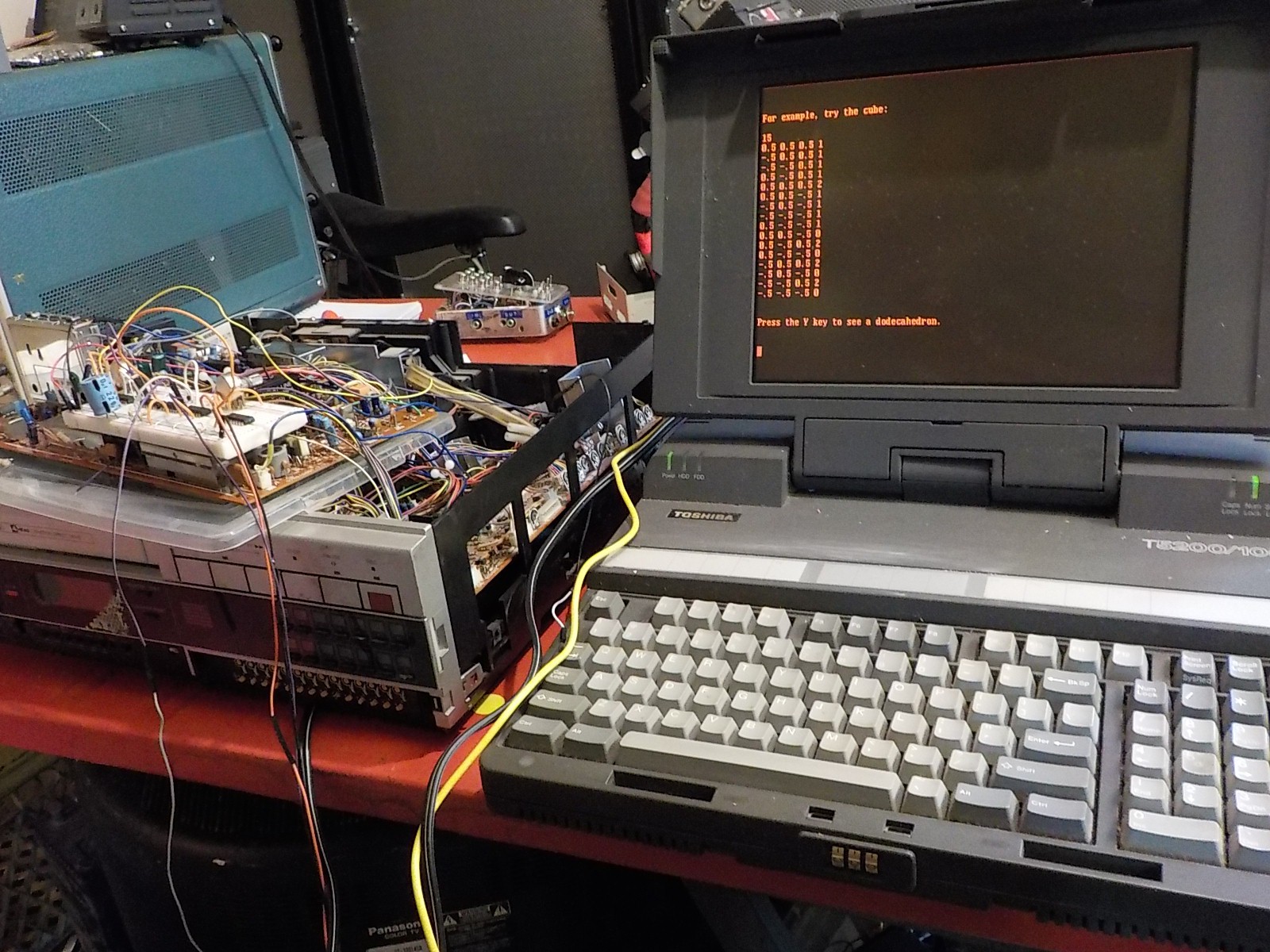
Composite video and 640x480 VGA have the same timing parameters and number of scanlines. The difference is that composite combines the sync signals, and colour channels into one wire. The R,G,B uses a chroma conversion where the amplitude of the signal represents brightness and phase shift gives the hue. Phase shift is based on a known frequency given during the vertical porch time known as "colour burst".

I tried sending the T5200's Hysnc and Vsync signals to the monitor while using the composite output to control R,G,B. This produces a black and white image (sort of).
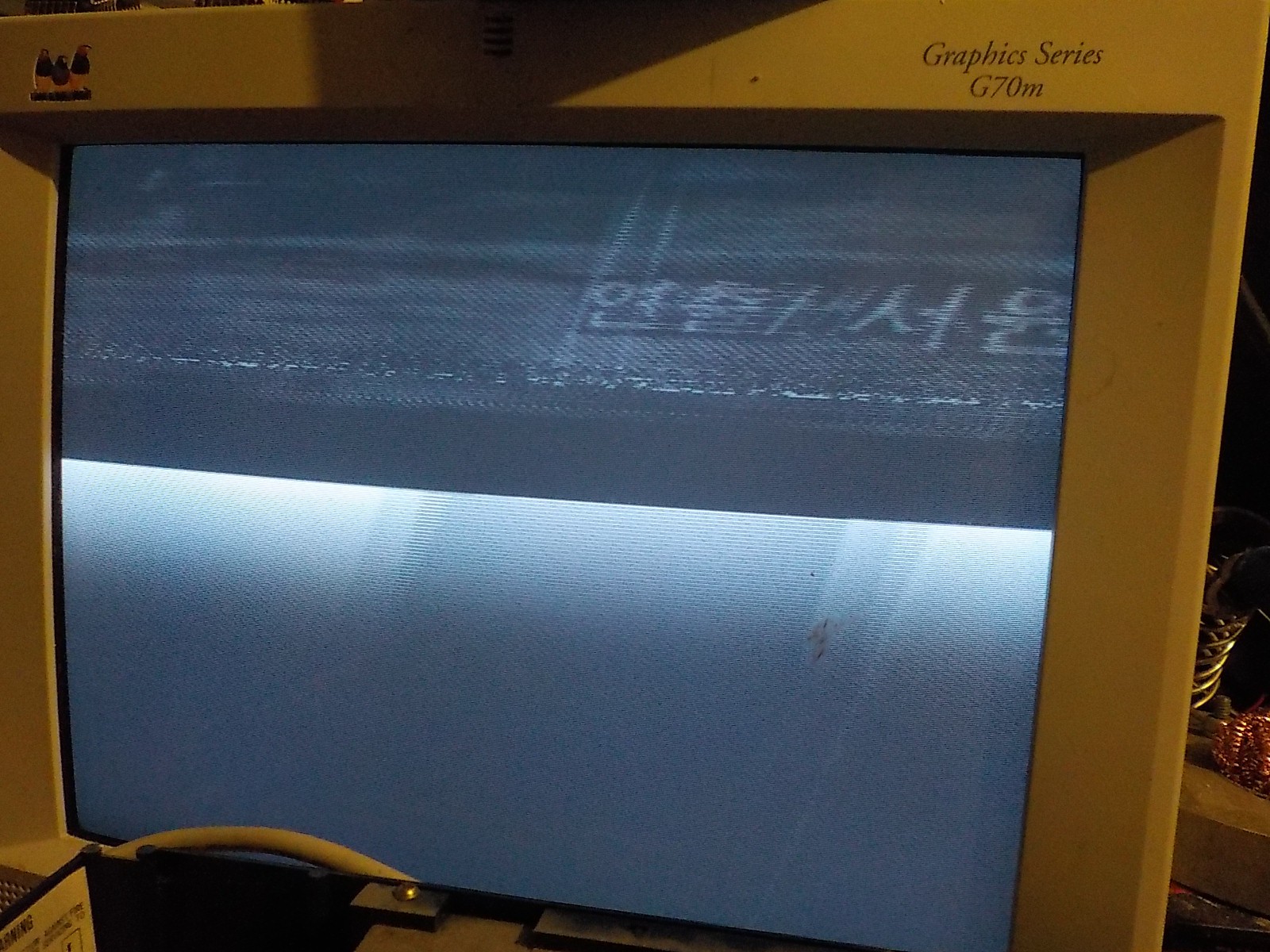
I had to take a dozen photos just to capture an image that was more than random squiggles and noise. 640x480x60Hz VGA and composite video have the same timing parameters in theory, but in real life there's a huge amount of instability in each signal. The composite video image is thrashing all over the monitor because it's not synchronized with the VGA signal.
I know the VCR will be using a phase comparator to keep its head and tape feed motors running at a constant speed relative to the VHS control track. The phase comparator takes a waveform from the VHS control tracks, compares it to a reference, then uses a low-pass of the result to adjust the head and tape feed motor speeds. What I want to do is find that circuit and replace the reference waveform with one generated from the external VGA sync pulses. This should synchronize the composite output from the VCR with the VGA output of the T5200.
I found an AN6344 chip, which must be the phase comparator I'm looking for. I was able to find a short Japanese datasheet too!!
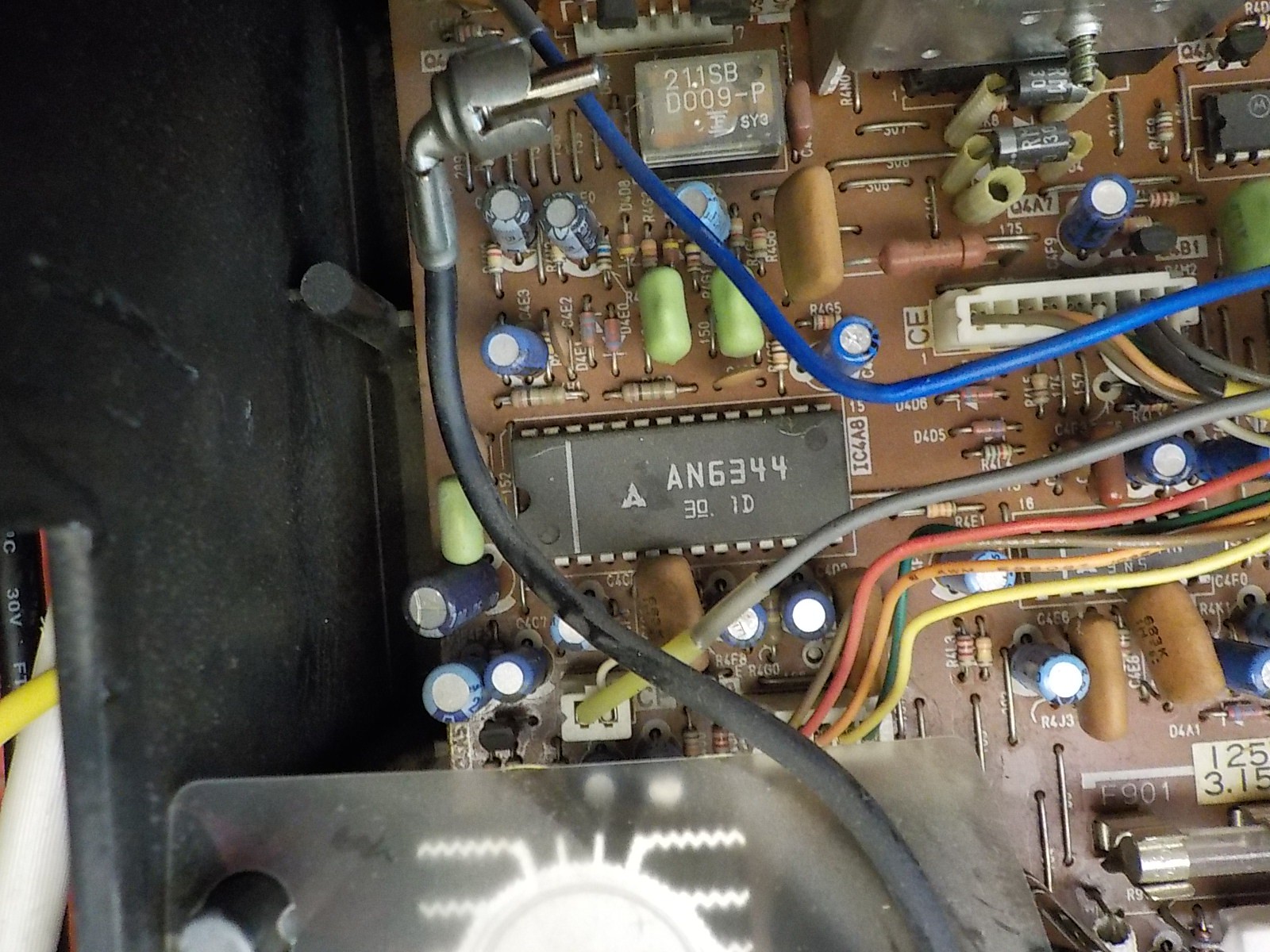

This chip is more than just a phase comparator. It's specifically designed for running a VCR and has several additional features. There's two different reference waveform inputs. One is used when recording and is extracted from an external video signal. The other is used for playing a tape and uses a reference created internally by the VCR. I want to cut this one and replace it with VGA sync.
From the datasheet I gathered that pin 24 is playback reference waveform and pin 25 is recording reference waveform. I tested it out and found it's reversed (pin 25 is playback reference waveform). I'm either reading the datasheet wrong or the designers of this VCR decided to wire it backwards and use the recording motor control circuitry to run the motors during playback and vice versa.
I also wired it up so the VGA red channel was coming from the T5200 while the green and blue channels came from the VCR. I found a pin inside the VCR that gave a sin wave at four times the frequency of the drive motor RPM and hooked that into the audio input while making the movie. You can hear the frequency change as I fiddle with the fast forward and rewind buttons.
The VCR vertically synchronization is very good. Horizontal synchronization is better now, but not as stable as I'd hoped. This comes from instability in the tape drive and head motors. You don't see the instability during normal usage because the TV gets its sync from the tape. The video from the tape is stable relative to the sync pulses in the tape.
I wanted the video to be more stable and attempted to design my own phase control circuitry. I was hoping that one referencing both the Hsync Vsync pulses would have better horizontal stability, but I couldn't produce anything noticeably better than the AN6344 circuitry. I think I've hit the hard limit on how stable the motors in a VCR can operate.
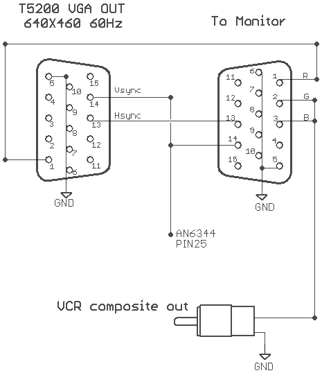
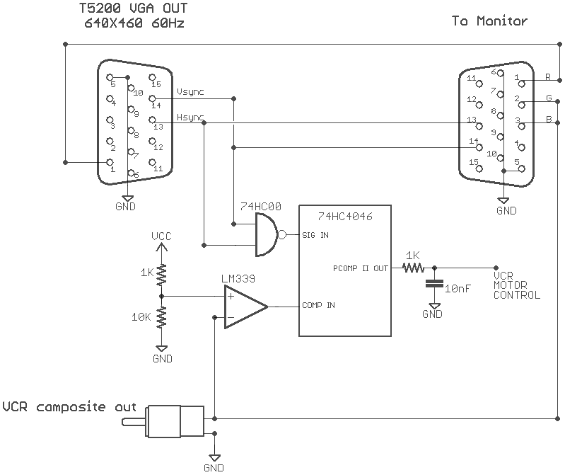 This is one of several designs I tried. It uses a comparator to extract the composite sync pulses from the VCR's output, then produce a second composite Sync pulse by NANDing the VGA Hysic and Vsync pulses. The two signals run into a 74HC4046 phase comparator II . The output is low passed then sent to the VCR's motor speed controller.
Discussions
Become a Hackaday.io Member
Create an account to leave a comment. Already have an account? Log In.