 Russell Kramer
My plan for the video circuit was to have each finger generate a unique set of curvy lines that follow its position. After that the curvy lines can be combined into a single signal and fed to a circuit that uses them to make interesting colour patterns.
I'm taking advantage of a 555's often ignored reset and VCO circuitry. By building a 555 astable circuit and resetting it on the horizontal crosshair output I produce several vertical lines that follow the finger back and forth across the monitor. I can create curves in the line sequence by applying a signal to the 555 VCO input. If this signal responds to the vertical crosshair output I end up with a pattern of curved lines that respond to the finger's vertical movement too.
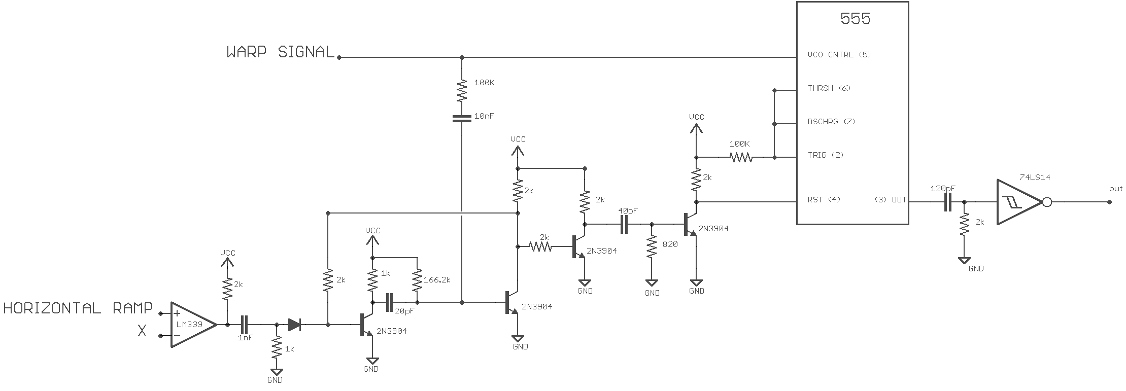
There's one of these circuits for each of the five fingers. It takes in the X position of a finger and a signal used to produce line curves (Warp). It produces a video signal of curved lines.
I cheated on the 555 astable circuit and didn't use a capacitor on pins 6,2 or a resistor on pins 6,2 and 7. This works because I'm running a bipolar 555 so fast that the width of the low pulse is how I like it without the delay caused by these components. They'll probably be needed with the much faster CMOS derivative.
The NOT Schmitt on the 555's output is used to make the lines thinner and to produce coloured lines on a white background. Without the inersion it's coloured lines on a black background.
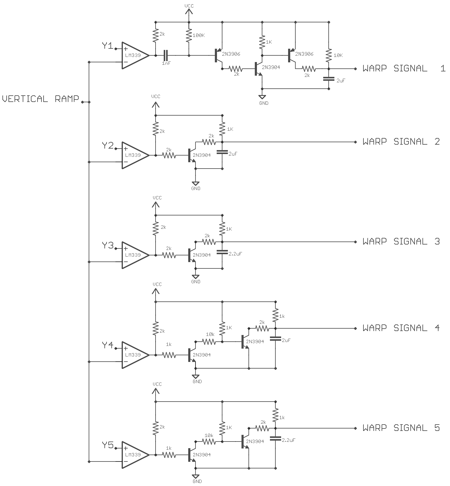
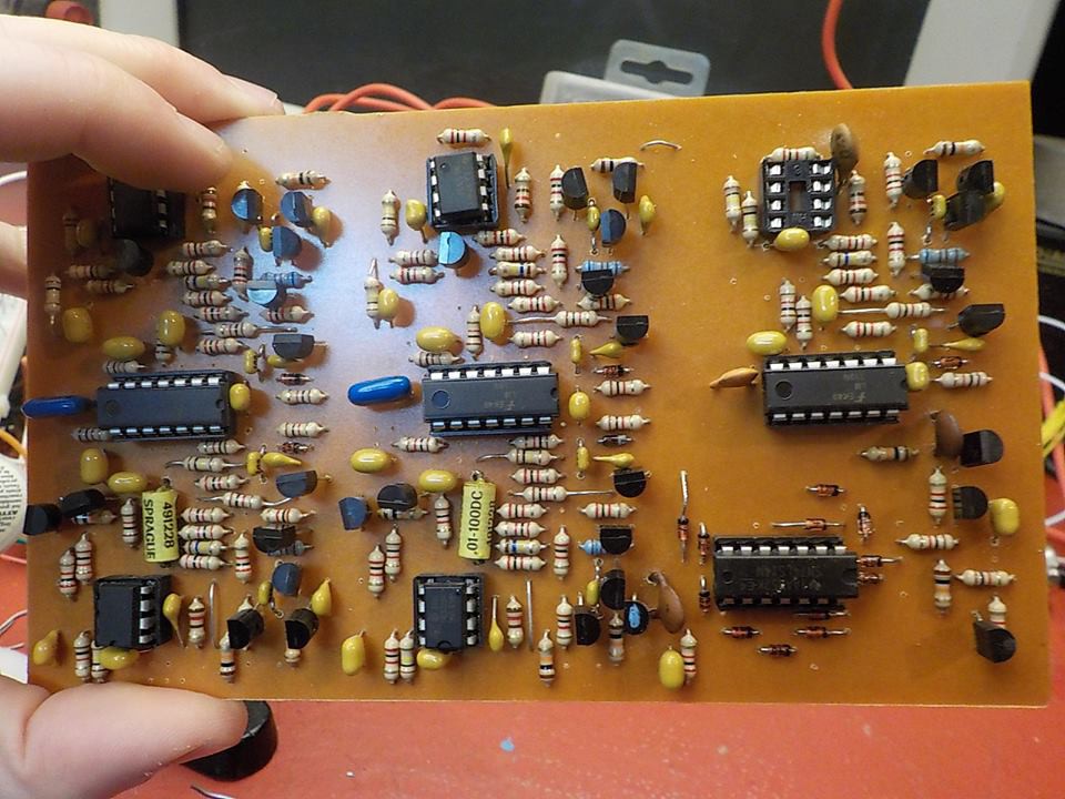
These are the five circuits used to give each finger a unique curved line pattern. Two of them are clones with slightly different component values. They're all variations on unregulated capacitor charge ramps. The 2uF capacitor at the end of the signal chain switches from charging to discharging when the comparator output goes from low to high because the vertical ramp has exceeded a Y signal.
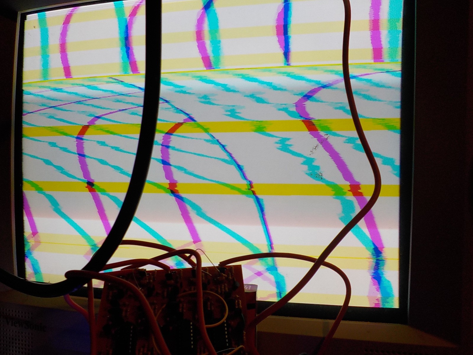
Picture showing the output of two different line generator circuits in pink and cyan. Z control was not implemented yet, so the lines are visible when no fingers are touching the screen.
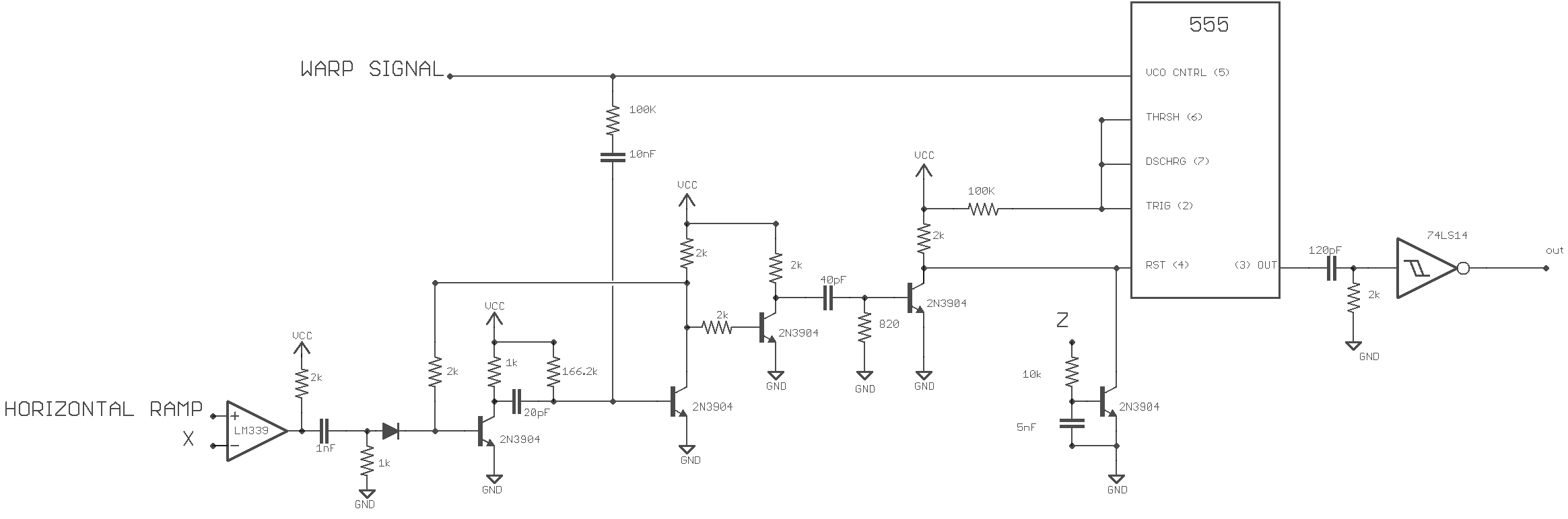
Next I added an interaction with the Z axis. Increasing the voltage from the Z input increases how long the 555 is kept in reset. This makes lines disappear and curve differently.
Here's me playing with the X, Y, and Z axis of a single finger.
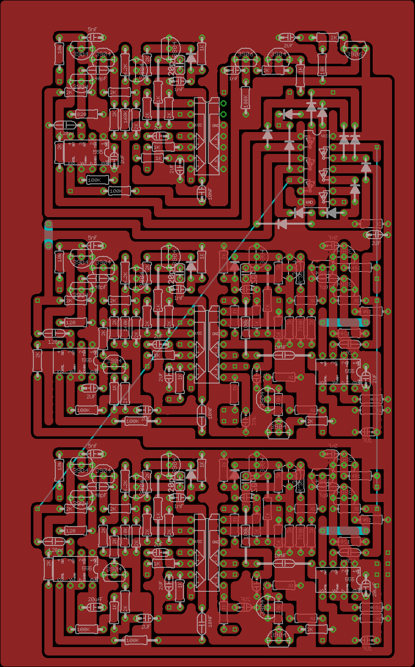
There's a few issues with the PCB. Somehow I forgot that all the ramp inputs to the comparators need to be connected together. I plan to make another version of this board combining it with the gradient board coming up next. The diodes around the Schmitt gates are part of the gradiant system.
Discussions
Become a Hackaday.io Member
Create an account to leave a comment. Already have an account? Log In.