 Russell Kramer
The gradiant board takes the five warped line video signals , combines them, and uses the result to produce colour patterns.
There are three RGB outputs on this board:
Coloured Lines
Uses a 74LS08 (quad 2-input AND gate) to draw coloured lines on a white background. Each of the five line signals gets a unique color. Red, Green, Blue, Yellow, Pink. The screenshots shown in the last log entry were produced by this output.
Rainbow Stripes
A 74HC4040 binary counter is clocked by a Schmitt relaxing oscillator controlled by a potentiometer. The counter is reset by any of the five line signals. This creates a pattern of rainbow stripes in the white space between the lines. Width of stripes controlled by potentiometer. The outputs of the 4040 are inverted because I need the pattern to be bright. The 4040 goes to 0b000 on reset which would be black without the invert.
The LEDs coming off the 4040 light up differently depending on how many fingers are next to the screen (producing line signals). Fewer lines means the 4040 can count higher between resets. I never pass up a chance to add cool blinky lights.
Blobs
I create a voltage that rises in the white space between the combined lines and falls when a line is encountered. This runs into an ADC formed with an LM3914 (bar graph chip) and 74HC147 (priority encoder). The 3-bit outputs of the priority encoder go to the RGB channels.
There are simpler ways to make a 3-bit ADC. I might redo this at some point in the future.
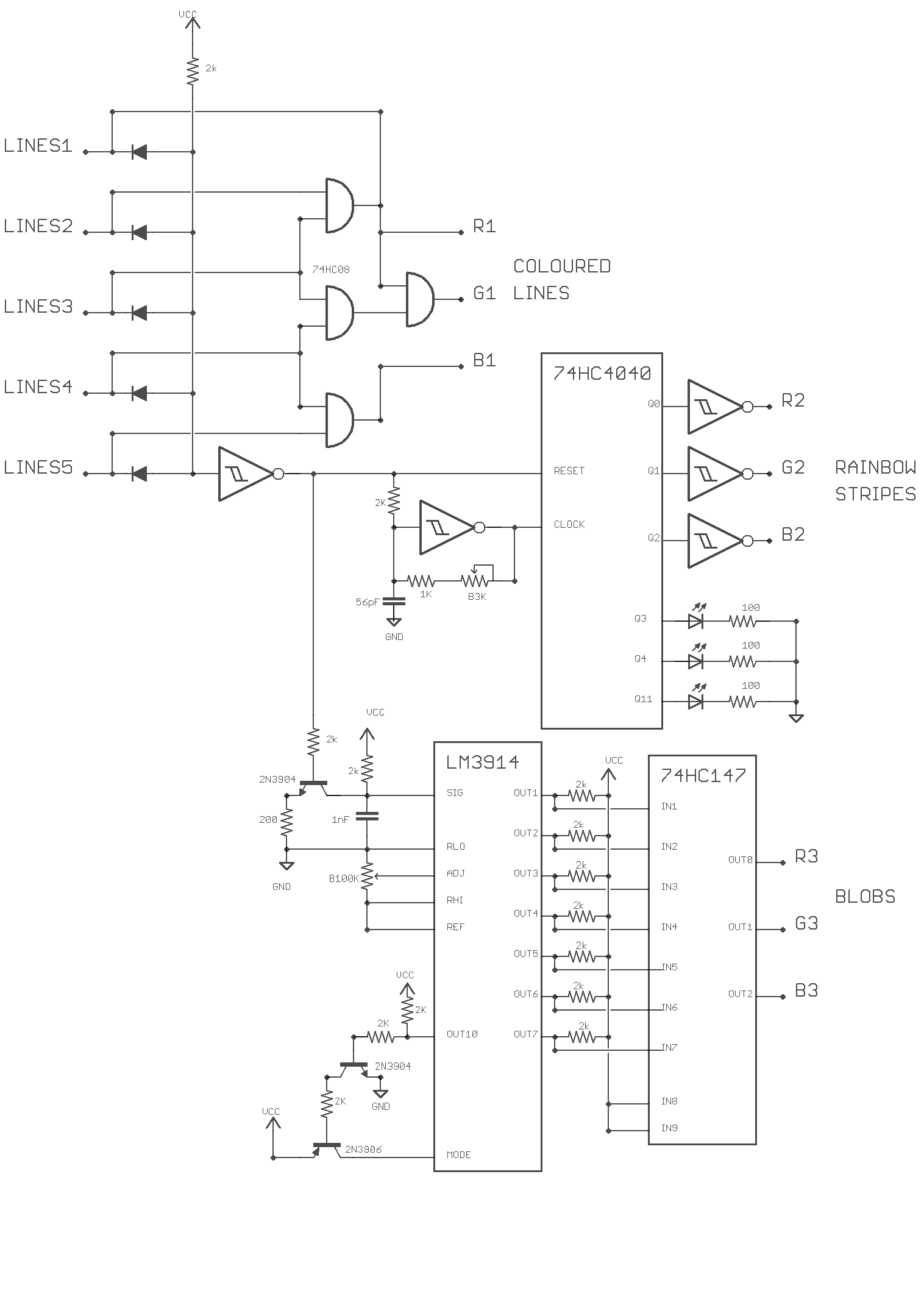
The diodes used to combine the lines signals are on the warped line generator board.
Screenshot of the blob output.
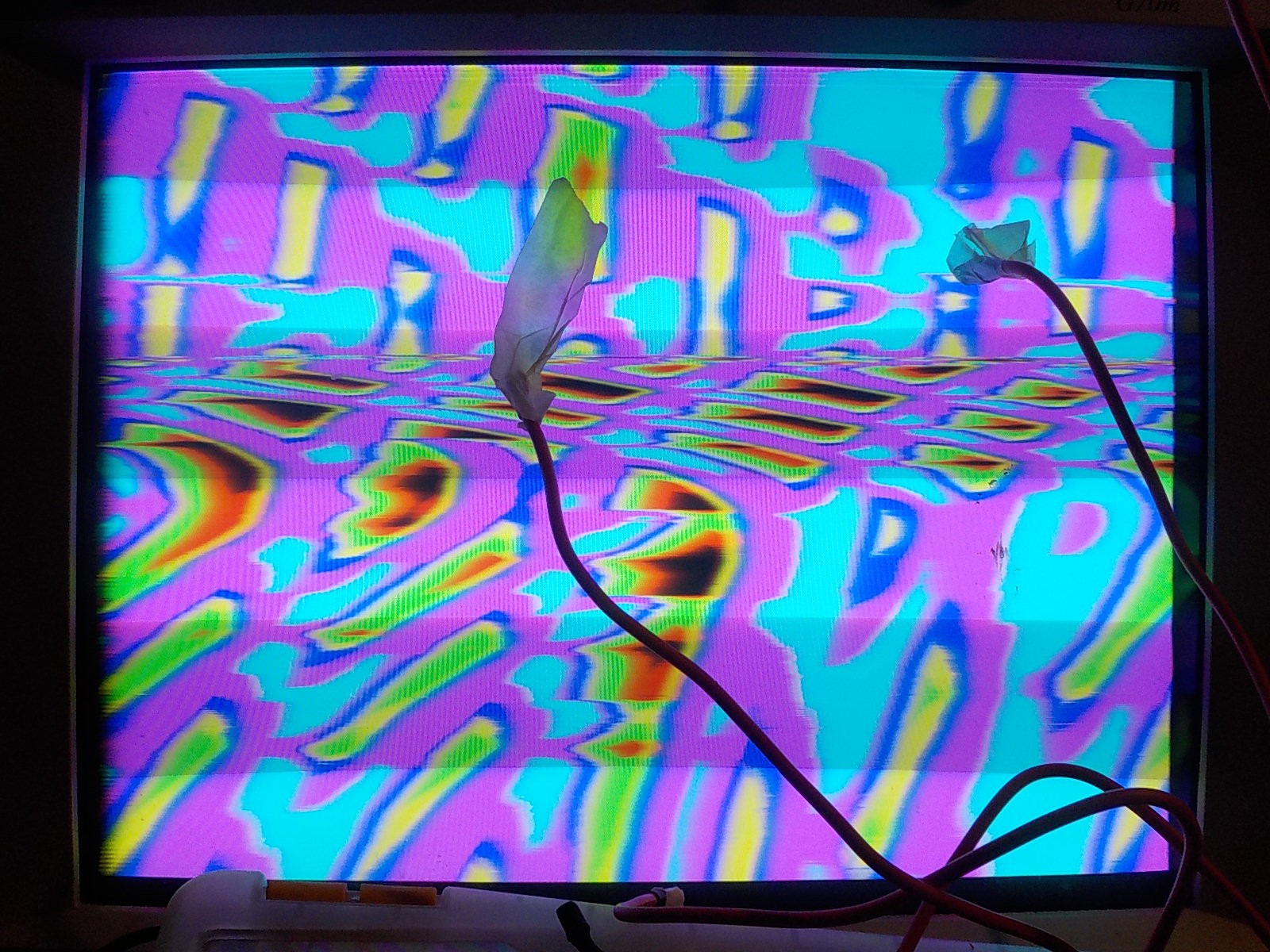
Rainbow stripe output was used when creating this video.
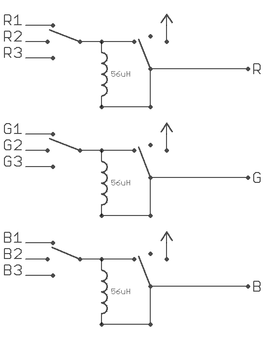
I used three sp3t switches to select between the different R,G,B outputs. This means I can have the red coming from the rainbow lines, the blue coming from the blobs, and the green coming from the rainbow lines; or any other possible combination.
I also added the option to force a colour channel to pass through a 56µH inductor or be connected only to VCC. Passing through an inductor causes a blurring effect. Blurring is applied to colour channels individually so it can produce new colours in the video output such as pink when red bleads into blue. Connecting a colour input to VCC limits the output pallet. A video that was showing all possible colours will be limited to reds, blues, and pinks if the green channel is always VCC.
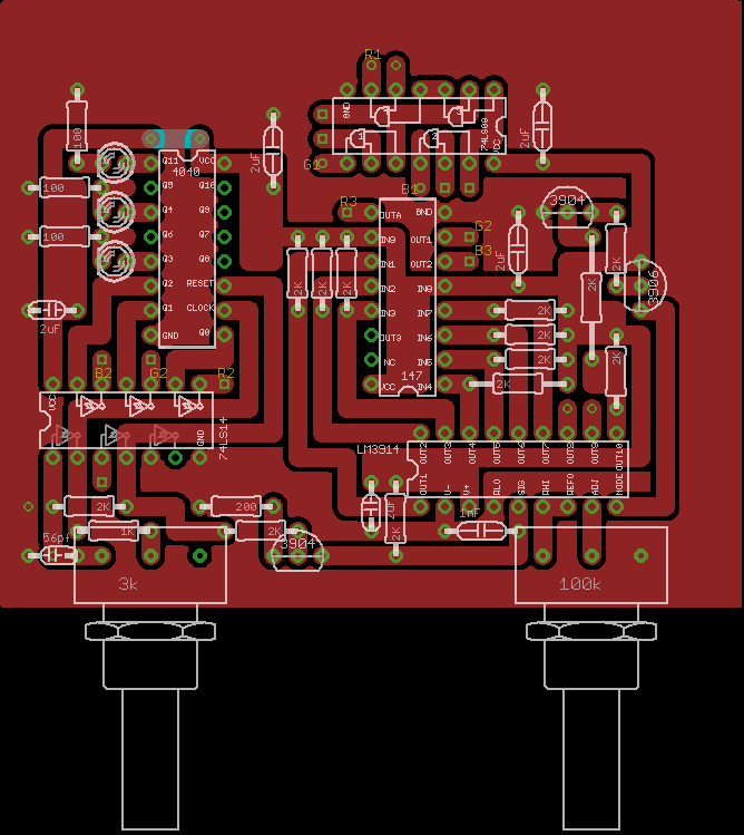
There's no PCB for this circuit because it was produced by soldering directly to panel mount components.
This video was produced with the red channel connected to the coloured line output with inductor blur, the blue channel connected to the blob output without blur, and the green channel connected to the rainbow stripe output with blur.
Discussions
Become a Hackaday.io Member
Create an account to leave a comment. Already have an account? Log In.