 Russell Kramer
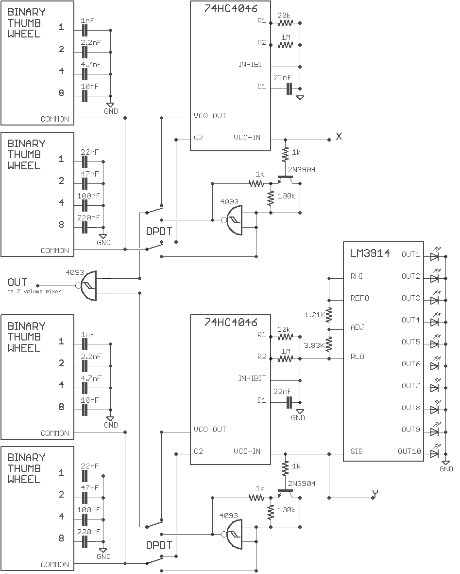
This is the first audio circuit I came up with. I don't like it. The design is similar to the one used in the Zapper project, but I over-engineered it. There's four oscillator circuits per finger total, but only two can be active at a time because I tried to be clever and have them share a variable capacitor. Of the two active VCOs one is controlled by the finger's Y position, and one is controlled by the finger's X position. One VCO is constructed with a 74HC4046 (phase locked loop) and one constructed with a 74HC4093 (NAND schmitt). The two oscillators respond somewhat differently to changes in finger position.
The base frequency of each VCO is controlled by a variable capacitor. The variable capacitor is built with a set of regular capacitors that connect in parallel through a pair of binary thumb wheels. I really should have only used one binary thumb wheel per variable capacitor; the fine tuning of the lower digits is unnecessary.
The circuit board also uses LM3914 to produce an LED dot display of the Y axes. This time one LM3914 per measured voltage instead of the overly-complex matrix multiplex design.
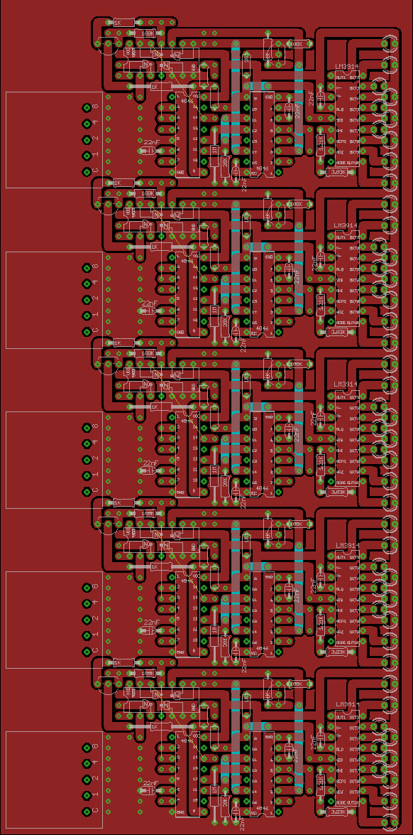
The PCB design isn't great. Way too many jumper wires.
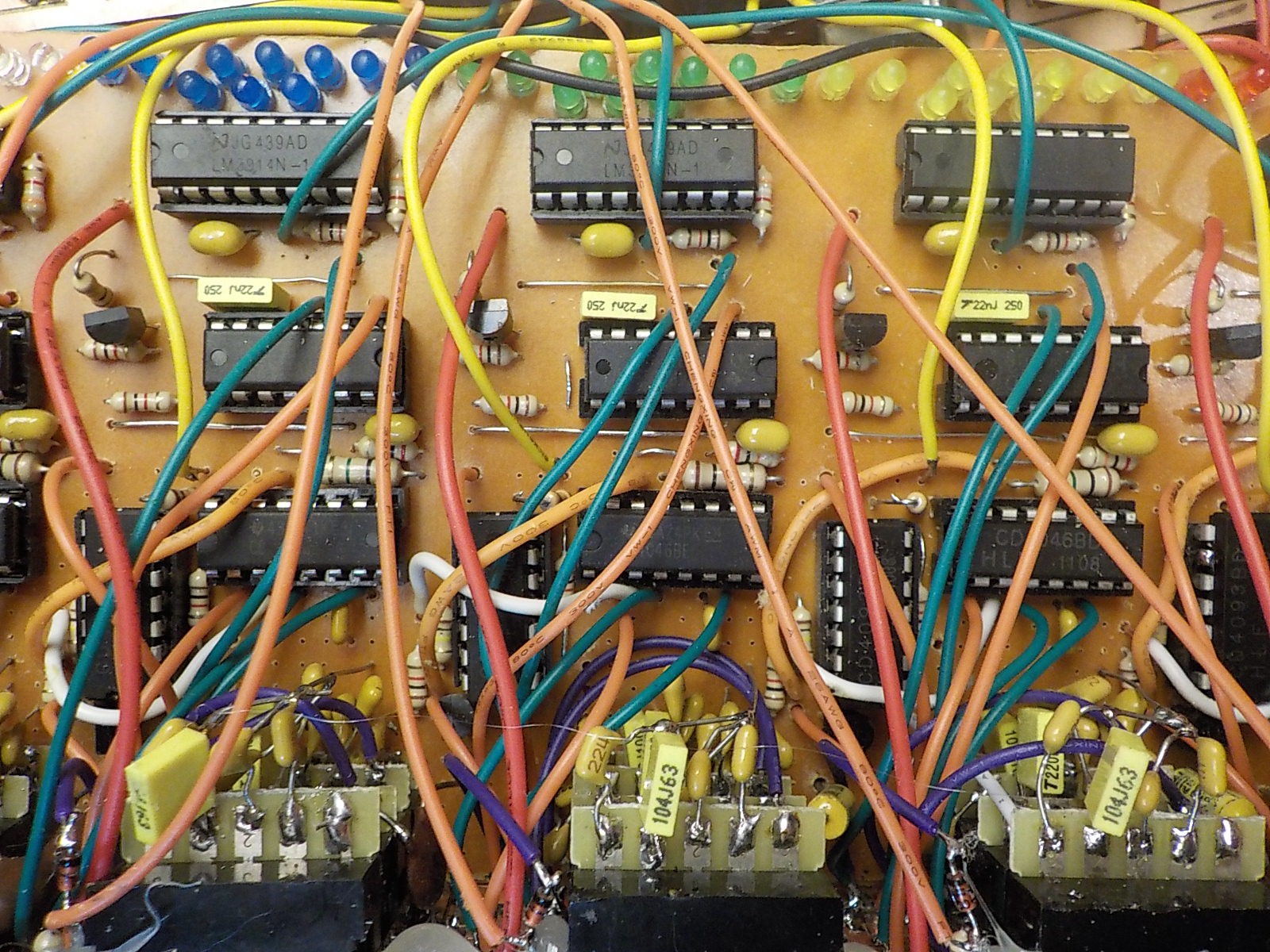
Here's a test of the audio circuit board. It's dirty buzzing sounds not music. I like the sound each finger makes by itself, but when multiple fingers touch the screen there's no distinguishable tones or beat. The video circuits produce the best patterns when multiple fingers are touching the screen simultaneously, so there's discord with how I want to use the glove.
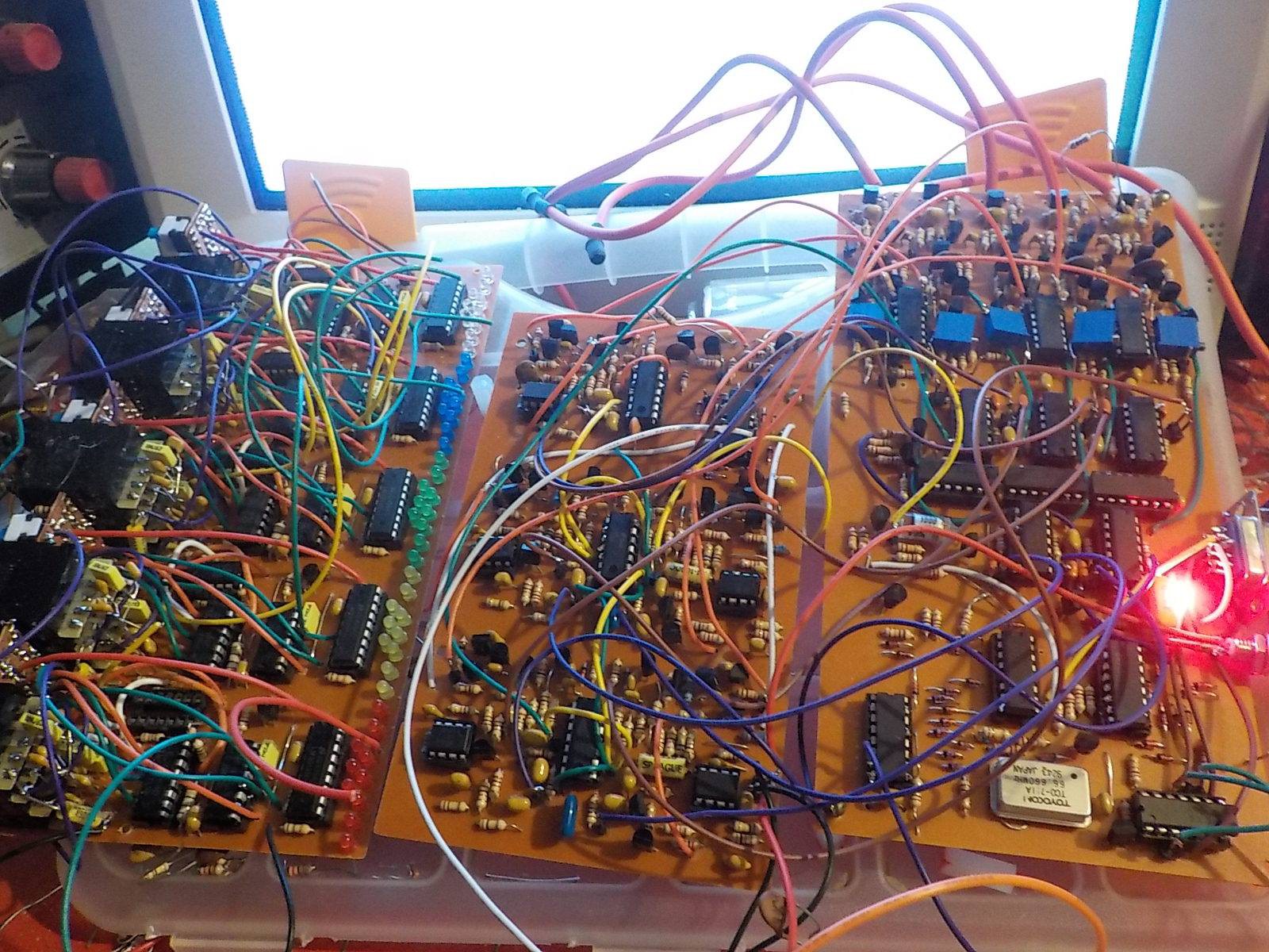
From left to right: Audio circuit, Video circuit, main control board.
Discussions
Become a Hackaday.io Member
Create an account to leave a comment. Already have an account? Log In.