THE STORY
You've heard it a million times: "The Arduino has analog inputs, why doesn't the Pi?". So, awesome hacker that you are, you decide to do something about it. But it wouldn't be any fun if there weren't some serious constraints. How about it has to be low cost, have low parts count, consist entirely of easy to acquire parts, and be simple to build even for novices? Something like PiFM, where the entire hardware interface is a piece of wire? (OK, a piece of wire is an over-simplification. It works, but you're supposed to add a filter consisting of something like 3 inductors and 2 capacitors or the FCC gets a bit grumpy.)
So you begin thinking: there is a well-known trick used with microcontrollers to measure analog values using a digital input. Here's how it works: you connect a capacitor from a GPIO to ground, and a resistor across the capacitor. You set the GPIO to output a one: this charges the capacitor. Then set the GPIO to an input, and the resistor will discharge the capacitor. All you need to do is measure the time for the input to go from a one to a zero. This works because a digital input can be used as a fairly consistent analog comparator, with a fixed threshold of approximately half the power supply voltage (for most CMOS devices). Typically this technique is used to measure the resistor or the capacitor. But you realize you can measure voltage if the the resistor is disconnected from the ground end of the capacitor and is connected to a voltage source instead. The voltage will, of course, have to be less than the input threshold voltage. But it CAN be below ground!
In microcontrollers it's easy to measure small units of time, but not so with the Pi. So you wonder: how can you sample a GPIO pin at regular intervals? Anything like a shift register will suffice, regularly sampling the input and combining the samples into a byte or word. And guess what, the Pi has two peripherals like this: PCM and SPI, which are both little more than shift registers.
However, there's a small problem: these peripherals can't change a GPIO from input to output automatically while sampling. But maybe there's a way to use another output to do this job? It could charge the capacitor through a diode while an output is high, and would have no affect when it's low. Then the sampling input could remain an input. How about if this reset signal was generated by the SPI output? It would just need to be fed the right data. And the SPI has to output data for the input to work anyway!
Next you review the design to see if things could be further improved. How about eliminating the capacitor? Since digital inputs have some parasitic capacitance associated with them, and the diode adds even more capacitance, maybe that will be enough. So you run some numbers to see if it will work: you pick a 1 megohm resistor (doesn't most test equipment have 1 megohm input resistance?) and take an educated guess that the input capacitance will be about 10 picofarads.
Using your old friend the RC time constant, and assuming a grounded input, you figure out that the capacitance will discharge to the Pi's threshold voltage in around 10 microseconds. This means the sample rate is around 100 kilohertz, which implies you will be able to measure anything lower than half that frequency. It looks like you'll be able to measure audio-range signals: not too shabby! But you realize you can do a little better: since the capacitance doesn't have to be charged up much past the threshold voltage, you can use two diodes in series. This has the effect of cutting the capacitance they contribute in half, decreasing the sample time.
And since the PCM peripheral is similar to SPI, you can add a second channel! Just use a second set of diodes from DOUT to DIN. You have to synchronize the PCM and SPI clocks, but you've done this before. And what's more, both peripherals can be serviced by DMA controllers! No processor intervention is needed during sampling. The only effect there might be is a small reduction in memory bandwidth.
Wow, you just designed yourself a two-channel audio band DSO (Digital Sampling Oscilloscope) using just 6 inexpensive parts!
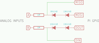
THE CIRCUIT
Here it is in all it's glory. Pretty simple isn't it?
THE SOFTWARE
Of course this circuit won't do anything without some awesome software. So you crank out the code in a jiffy. (Okay, it actually took several weekends of work. You're not as good a hacker as you thought.) As it turns out your original estimate of the input capacitance wasn't far off: it's actually close to 20 picofarads. And the two inputs have different capacitances and/or thresholds. But after changing the code to account for this, your sampling rate is still just over 50 kilohertz. This means you can easily capture 20 kilohertz signals: that's the whole audio band!
THE REALITY
That's the end of my little story. There were actually a few iterations of the circuit, and I started by using the PCM peripheral instead of SPI.
There are also many problems with the circuit. Here is a partial list:
- Although the input resistance is 1 Megohm, current is not drawn smoothly, so it could introduce noise into the measured circuit. This also means the signal should be DC coupled.
- The resolution is only about 6 bits: that's not great, but still usable to get the general idea of signal shape and timing.
- Since there is no low-pass filter on the inputs, aliasing will be a problem.
- The sample values must be corrected in software since the circuit is horribly non-linear. This must be done differently for each channel, and probably for each Pi.
- As designed the input range is 1V p-p, so you'll need to attenuate anything greater than this with external circuitry.
- It's probably sensitive to temperature.
- There is a noise spike around 4KHz. I'm guessing it's aliased power supply noise.
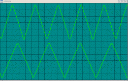
TL;DR: it isn't very practical. I built it solely to see if it could be done, and to see how accurate it was. But even so I've been surprised at how well it works. Every time I thought it was measuring incorrectly and double-checked it with a 'real' oscilloscope it was spot on. Turns out the PI sound output (Future project: use the Pi as a signal generator!) is pretty crappy...
Here's a screen cap of a scope display program I wrote, displaying actual data from the project. There are some jaggies at the bottom of the waveforms - those are from the non-linearity combined with the small sample resolution.