 Alvaro Villoslada
Today I have been working on the integration of the EMG control (using Mumai) with the latest version of Dextra. EMG control was already implemented in the first Dextra prototype, but it was not yet implemented in the current version of Dextra, the one that can be found here on hackaday.io and on its repo. In the following video, a demonstration of the implemented myoelectric control is shown.
Developing version 1.0 of Dextra has been a lot of work (and there are still things that I would like to implement). Besides greatly modifying the mechanical design, a lot has been developed on the software side: a new firmware that includes closed-loop control, a serial communication protocol made from scratch, the control GUI... All this work delayed me on the integration of the EMG control, and it was something that had to be done as soon as possible, considering that the project started as an attempt to develop an open-source and low-cost myoelectric prosthesis. However, I could not implement the EMG control before finishing at least the new firmware and the communication protocol, since controlling the hand depends on how it works and how it receives the motion commands.
So, how does the implemented myoelectric control system (MCS) work? First of all, the MCS runs on a separate microcontroller, not in the Teensy that runs the Dextra firmware. In the first Dextra prototype, both the hand controller and the MCS ran on the same microcontroller. But as I mentioned on the previous project log, the new firmware is quite more complex, with a bunch of interrupts firing here and there, so adding a MCS to the equation would probably make something not work properly, mainly because the EMG signal sampling also depends on a timer interrupt. Currently, the MCS is implemented on an Arduino Nano.
EMG data is acquired with one Mumai circuit
from the flexor digitorum profundus muscle on the forearm,
which is in charge of flexing the fingers. The output of the EMG circuit is connected to one of the analog inputs of the Arduino to digitize it. The EMG signal bandwidth goes from 20 Hz to 500 Hz, so it has to be sampled at least at a 1 KHz rate. To this end, a function that reads the analog input is set to run every 1 ms using the MsTimer2 library. With this simple configuration, the raw EMG signal is acquired.
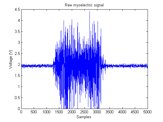 The simplest form of EMG control, and the easiest to implement in a microcontroller, is the threshold-based MCS. These controllers compare the amplitude of the EMG signals with a predefined threshold. If the amplitude exceeds the threshold, a hand close command is generated, and if not exceeded, a hand open command is generated. However, a raw EMG signal, like the one in the image above, cannot be used in a threshold-based MCS; it has to be processed. This is why most "hacker-friendly" EMG circuits output only the amplitude of the signals, doing the signal processing (rectification and smoothing) on the hardware side, so they cannot be used to acquire raw EMG signals (which is quite useful depending on the application). For this reason, I designed a circuit that outputs the raw signals for a more general use, with which the signal processing is done on the software side.
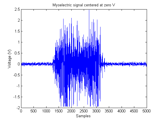
As the EMG circuit is powered with a 0-5 V supply voltage, the EMG signal is centered around 2 V, to measure the full range of the signal. In order to rectify the signal, first its baseline voltage has to be lowered to 0 V. On power-up, the first calibration step of the MCS, the zero level setting, is in charge of that. In this first mode, the user has his muscles at rest for 30 s. During this period of time the EMG signal is measured. With the muscles at rest, the acquired signal is just the baseline voltage. After this time, the average of the measured signal is calculated. The resulting value is subtracted for now on from all the values converted by the ADC, so that all new measurements are centered around 0 V.
 Now, rectifying the signal is just a matter of applying the abs() function to any new measurements.
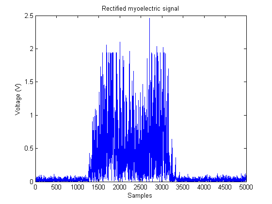 The rectified signal is still not suitable to be used in a threshold-based MCS. In order to compare it with the activation threshold, the signal must be smoothed to obtain a measure of its amplitude. This smoothing is performed computing the moving average of the incoming rectified signals. Specifically, the technique used to calculate the moving average is the so called running moving average, which works by subtracting out the mean each time, and adding in a new point. The great advantage of this method is that it does not require any storage of previous data values, and minimizes divisions which are computationally intensive. This makes it very suitable for its use in microcontrollers with low RAM and low CPU speed, as the one used in Arduino.
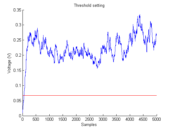
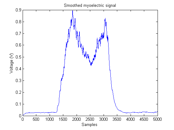 The last step before being able to control the robotic hand is to set the activation threshold. This setting is done during the second calibration step, after measuring the baseline voltage. In this step, the user makes a strong muscle contraction for a period of 5 s. This contraction must not be as strong as to be tiring and uncomfortable for the user. During this 5 s period, the maximum value of the smoothed EMG signal is calculated. This value is the so called maximum voluntary contraction, or MVC. From the MVC, a relationship is established between its value and the activation threshold. The value of the activation threshold is the 20% of the measured MVC.
This mode is a very important feature of the implemented MCS. When one
has been using a prosthesis during some time along the day, the EMG
signal amplitude starts decreasing and the MCS starts failing. This is
due to muscle fatigue: the more tired the muscle is, the smaller the EMG
signal. If the activation threshold has a fixed value, the EMG signal
amplitude may not reach its activation value. However, if a variable
threshold is used, it can be adjusted to the muscle contraction level.
With this mode, the user can set the MVC value with which he feels
comfortable at any time. This way, the activation threshold always has a
value reachable by the EMG signal, no matter how tired the user is, and
the MCS does not fail.
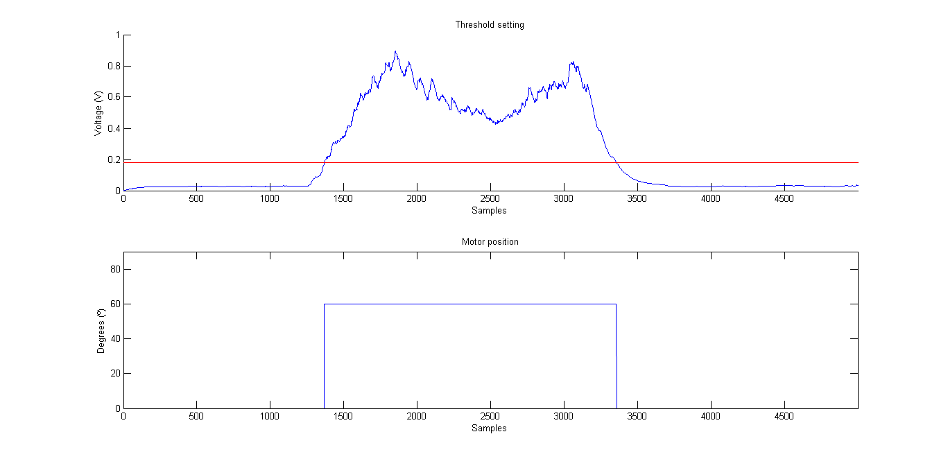
With all set, the robotic hand can now be controlled. During control mode, the EMG signal is sampled, rectified, and its moving average is calculated continuously, as explained before. Every time the MCS detects that the amplitude of the EMG signal is above the activation threshold, signaling a voluntary contraction, the finger positions corresponding to a closed hand position are sent to the hand microcontroller through the serial port, using the Synapse protocol. On the other hand, if the amplitude of the EMG signal is below the activation threshold, the finger positions corresponding to an opened hand position are sent.In the following video, it is shown how the implemented threshold-based EMG controller works.
 As with the rest of the elements of this project, the code that does everything described above is in the Dextra repository. It is not yet merged into the main branch, since I am still polishing some details, but it can be found in its corresponding development branch.
Discussions
Become a Hackaday.io Member
Create an account to leave a comment. Already have an account? Log In.