 Alvaro Villoslada
As I said in the project details, I think a position controller alone is not enough to have a fully functional robotic hand. With only a position controller, to grasp any object without breaking it (or without risking damaging the hand), the approximate finger positions to grasp that object must be known beforehand. For example, to grasp a bottle, the hand must roughly know what are the positions of each finger to grasp that particular bottle. To grasp a ball, a different set of positions is needed, and so on for any other object. Thanks to the underactuation mechanism used in the mechanical design of Dextra, the exact positions are not needed, since the fingers can adapt to the shape of the grasped object. But it is obvious that it is not practical to have a preprogrammed set of grasps, because this set can be enormous and the task of programming each one can be very time consuming.
For me, the solution to this problem is to use a force controller. In fact, I think the ideal solution would be to use a hybrid position-force controller. With the position controller, the fingers could be configured to adopt a preconfigured pose from a small set consisting of the main hand grasp types (in the robotics field this is known as pregrasping). From this pregrasp pose, the fingers would be commanded to close, and the final grasp would be controlled by the force controller. Thanks to the adaptive grip, the fingers would conform to the shape of the grasped object.
But before working on hybrid controllers, I have to implement a force controller. The first question one asks when developing a closed-loop controller is, how do I measure the variable I want to control? In this case, where I want to control the force exerted by the fingers, the first answer that came to my mind was: force sensing resistors. FSRs are small and have a low profile, so its integration would not increase the volume of the robotic fingers, they are very easy to use (they are variable resistors) and they are moderately priced. The question is, how many sensors would each finger need? Just one on the fingertip? One per phalanx? Ideally, the best option is the second one, but this would increase the cost and complexity of the system. But even if only one sensor on the fingertip is used, there is another problem: wiring. Having sensors on the fingers implies wiring them up to the micrcontroller. Integrating cables into an articulated mechanism such as a finger has a certain complexity, but for me the biggest problem is that the assembly of the hand would be more complicated. And one of the main objectives of this project is precisely that the hand has to be easy to assemble.
A while ago, a pair of colleagues from my university implemented a zero-gravity compensator for the arms of a humanoid robot. To measure the torque exerted by the motors, instead of using a force sensor, they modeled the motors and used their current consumption to get a torque estimation. I decided that this is a very suitable method for this project, because a single sensor can measure the total force exerted by one finger, and the sensors can be integrated into the control board along with the microcontroller and the rest of the components, without using wires.
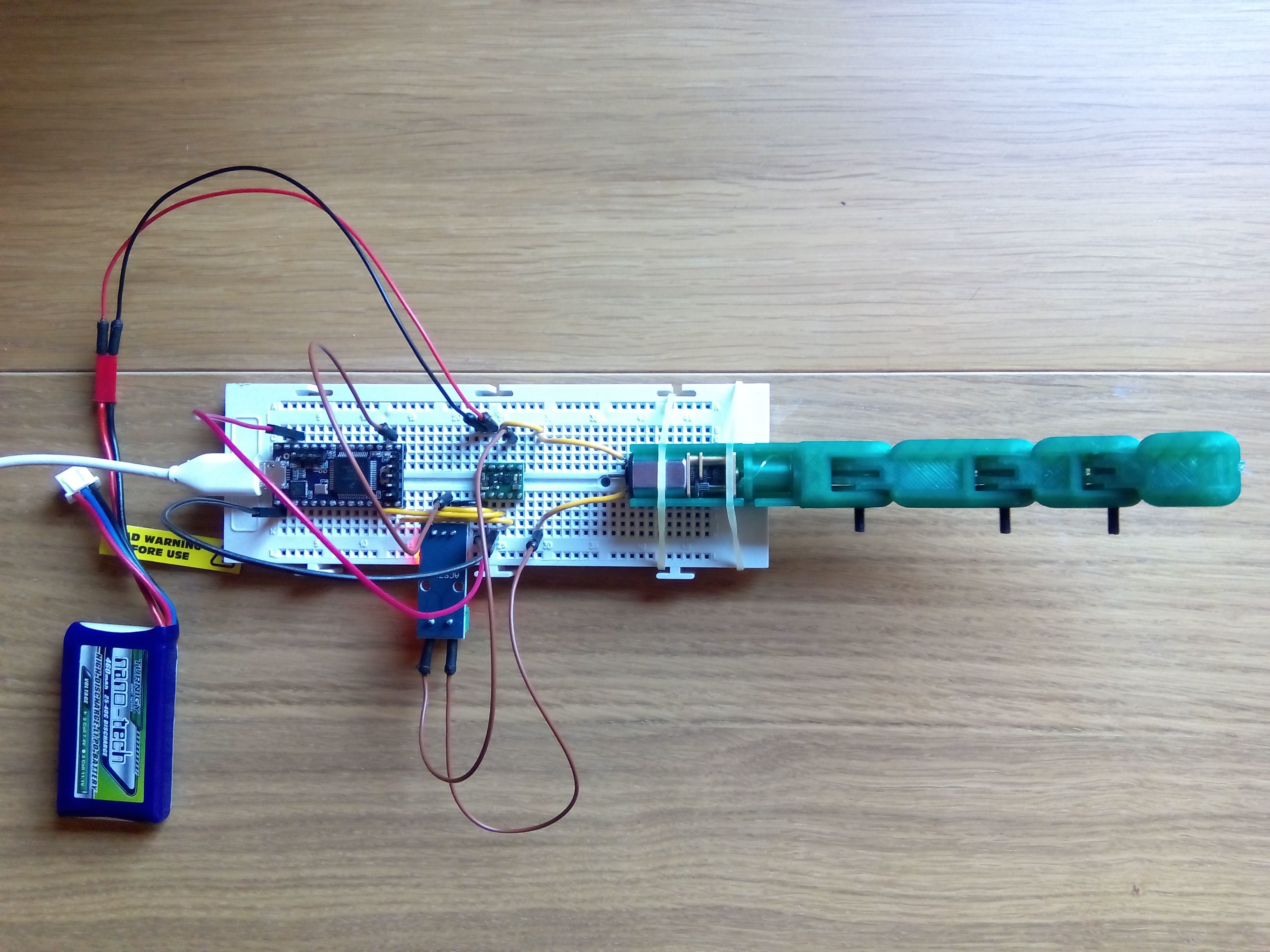
To begin testing this idea, I bought a Hall effect current sensor, the ACS712 (the model that measures up to 5 A). I printed and assembled a new finger module without soldering an encoder to the DC motor, since the feedback for the control loop is provided by the current sensor. With all the necessary elements, today I have set up the following test bench.
 I have decided to use a PID for the force controller, just like I have done with the position controller, so to get things moving I only have had to adapt the control code of the Dextra firmware. The results of the first force control tests can be seen in the video below.
For a proof of concept, the results are not bad at all! I have had a couple of problems related to the current sensor. First, the measuring range of 5 A is too large for the current drawn by the motors of the hand, which reach a maximum of 1.6 A stalled. This means that with a proper sensor, the current could be measured more accurately. The second problem has to do with the noise of the sensors. The ACS712 is very noisy. This can be somehow fixed by soldering an extra capacitor at the output, but this week (the final week of the Hackaday Prize!!) my soldering iron has decided to stop working. I have managed to reduce this problem by filtering the noise applying a running moving average to the sensor measurements, but this introduces some delay between the real measurement and the filtered one. All of this makes me think that what I need is to design my own current sensor tailored to the needs of the project, but that will have to wait a little bit.
Discussions
Become a Hackaday.io Member
Create an account to leave a comment. Already have an account? Log In.
Hi, have you thought of using motor controller that has the current sensing built in? I attached 2 references for this. Regards, Marcus
https://blog.arduino.cc/2012/06/15/quick-tutorial-current-sensing-for-dc-motors/
https://www.olimex.com/Products/RobotParts/MotorDrivers/BB-L298/open-source-hardware
Are you sure? yes | no