 Arya
AryaI sometimes go on an eBay bidding spree, trying to get items of <1-2$ price which I don't really need right now but might need later. The same was with a nice LED dimmer (which I'd never plan to buy!) I found and subsequently won:

This is how these look like. I threw it somewhere and forgot about it. I also have a really cheap rotary tool which looks like this (only black, this seems to be just a rebranded version):
 It has a barrel jack connector on a cord for 12V power. I don't have the current consumption figures, sorry. Anyway, I needed a speed control for it because of noise produced, necessity to sometimes operate more smoothly and thus slowly and the fact that my tool started to develop some bearing problems, and speed might be a factor which I might want to take into account when I'll get the same tool to replace this one. I remembered that I had this dimmer somewhere, found it (the most difficult part in all this, honestly) and disassembled it:
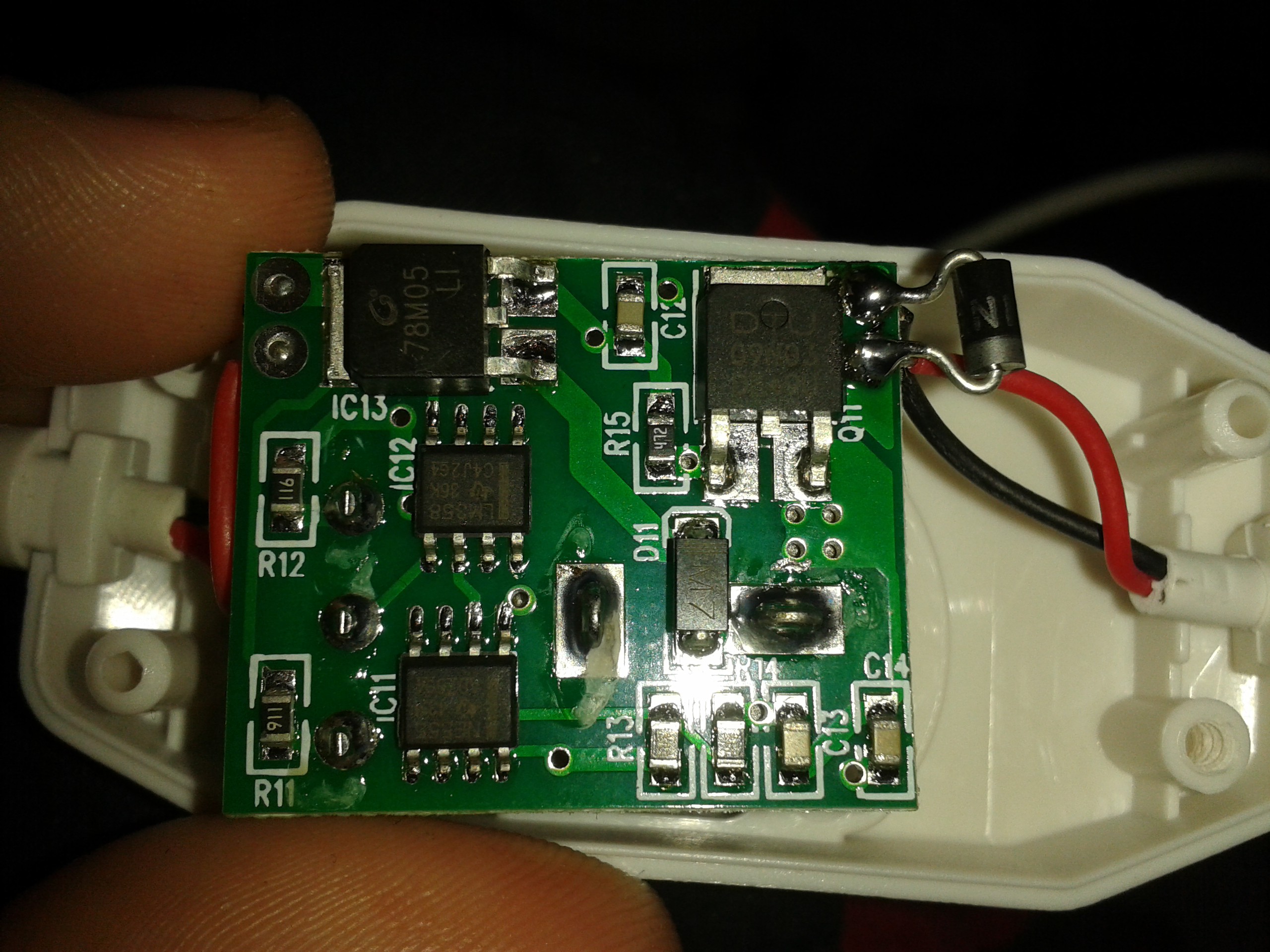
It's a pretty well-built circuit. Beats many of Chinese electronic pieces like this (typically epoxied/with sanded down IC markings/unknown components/etc.). It is clear (I might be wrong though) that NE555 is producing some sort of PWM to drive the MOSFET, and the PWM is controlled using the potentiometer (which also has an OFF feature, that is, it has a switch which's connected when the potentiometer is turned to one of the extremes). It also has some more components, like an op-amp, which purpose I'm not sure about - but I'm sure it was necessary if these guys who are typically cutting corners by removing every single not-so-necessary component left this op-amp in the circuit (maybe they have them on clearance, after all). Note - the deadbuggy-diode wasn't originally in the circuit...
Ah, about the diode. So, I was looking on whether this thing could substitute a speed control for my rotary tool, and it looked as if it easily could, with only difference being that LED strips which this thing was intended to drive don't typically generate EMF when being switched, especially switched with PWM. A diode, as we all know, easily prevents the driver from damage - and so it did. I added a diode, assembled the thing and connected it in series with my rotary tool - and it worked as a charm.
I just now realise it could blow some components if those red/black wires on the right were not representing the polarity (I didn't even check that with a DMM), but they were correctly-colored. Once again, quite a surprise. Also, it's still good for driving LEDs!
I plan to get some more of those dimmers to see if this would be good to base a soldering iron dimmer upon (with a 12V/2A soldering iron and a built-in thermocouple). I'm sure I'll be better off making my own board for this, but nevertheless I'll consider this if I need a minimum effort option. Also, in case of rotary tool, I think this circuit could even be embedded in the rotary tool itself (all those wires are bulky, after all). You'd want to make the potentiometer head smaller though =) Anyway, it's a nice potentiometer-PWM-MOSFET thing, and you could use that in one of your projects too.
Discussions
Become a Hackaday.io Member
Create an account to leave a comment. Already have an account? Log In.