 Moritz Walter
Charging circuit
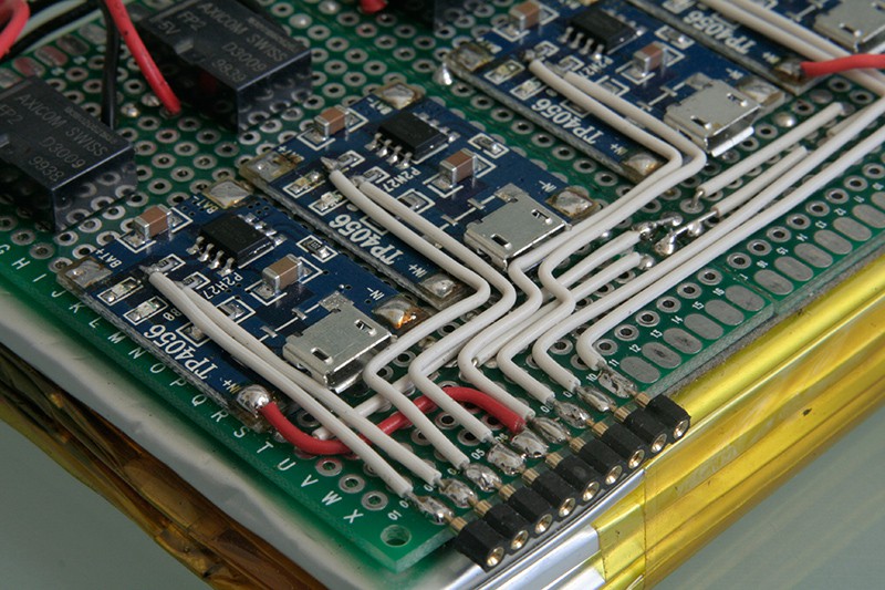
Meanwhile I've managed to fully assembled the charging circuit I described in the previous log. I backpacked it on top of the four LiPo cells.
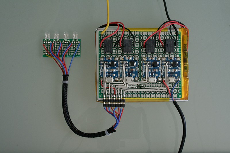
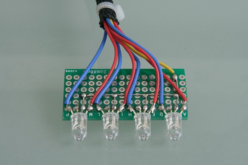
I also added an external board with four common anode RGB LEDs to display the status of each cell on the back of the speaker. "blue" means full, "red" means charging.
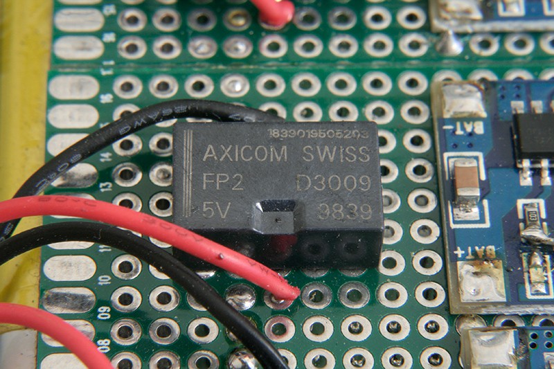
Below you can see one of the Axicom FP2 relays, it's super tiny but still can take high voltages. However, the switching current is 2A max., which is the bottleneck for this charging circuit, so per specification, the maximum charging current of an individual cell is also 2A max., and the maximum current to draw from the entire pack is also 2A max. Fortunately, the TP4056 can only deliver 1A and the amp will also draw no more than 2A.
The TP4056 modules were surface mounted to the perfboard with their input and output pads. I also cut the connection to the onboard LEDs and bodged the LED signals to a pin header for connecting the external RGB LED board.
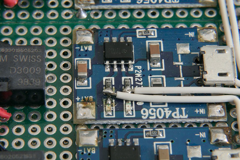
The wire bodging was tedious. Definitely an argument for having some nice PCBs made next time I use this circuit, and then of course skipping the modules and designing my own TP4056 circuit. Below picture also shows how the charging circuit sits on the LiPo cells.
The amp
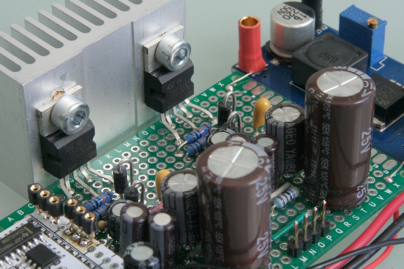
In the tradition of this project, also the amp was prepped on a perfboard, because well, why not. AB amps are dying out anyway.
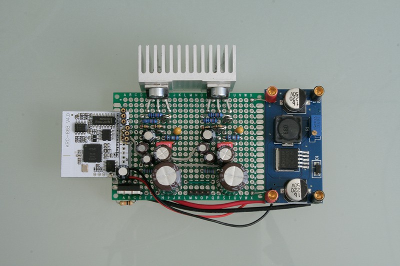
The DC/DC converter was also attached to the perfboard it to save space. It supplies power to the KRC-86B bluetooth module and USB charging ports.
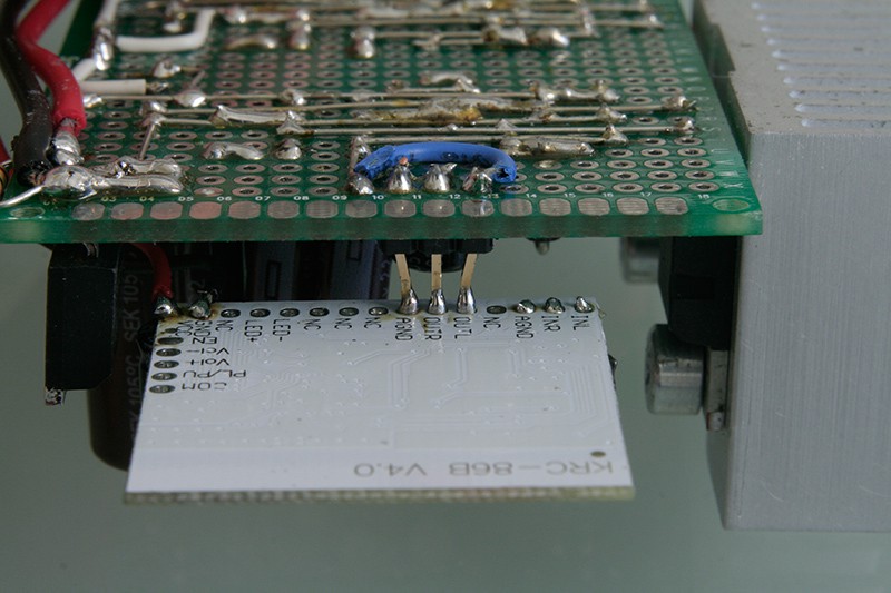
I tried to route this as clean as possible, but then thought I might as well add a MOSFET to turn the amp on and off from the bluetooth module's 'EN' output, which goes HIGH when the module has successfully connected to a host device. So the right lower corner is a bit messy :)
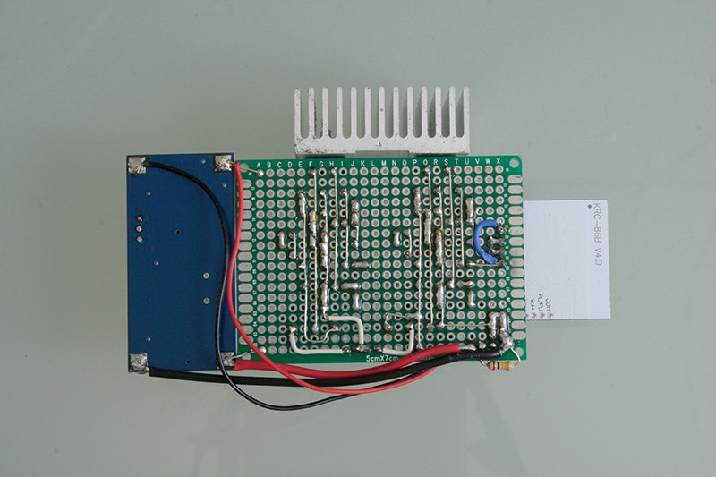
The KRC-86B bluetooth module sits on a pin header attached to the amp, which makes it easier to mount the whole thing in the shell later.
The TDA2030A are attached to a somewhat a bit too large heatsink from the drawer. If I measured everything right, it should fit though.
Discussions
Become a Hackaday.io Member
Create an account to leave a comment. Already have an account? Log In.
Hey, it turns out to be very very good looking! =) Cheers!
Are you sure? yes | no
Thanks!!!
Are you sure? yes | no
Beautiful, never thought about using relays for this, makes so much more sense than a switch with 5 poles to switch...
Are you sure? yes | no
Thanks! Totally, especially since toggle switches with x pins usually cost x^2 :/
Are you sure? yes | no
perfboard = art ;)
Are you sure? yes | no
Totally Agree!!
Are you sure? yes | no
@esot.eric @danjovic thanks :)
Are you sure? yes | no
+1 :)
Are you sure? yes | no