As a long-time diabetic, I finally made the switch over to an insulin pump. Part of using a pump means changing infusion sets periodically. An infusion set consists of a tiny tube inserted under the skin, with a plastic piece that connects to a detachable piece of tubing which connects to the pump. These are meant to be replaced every 2-3 days. Beyond the third day, the skin around the infusion site begins to scar and can significantly reduce the absorption of insulin.
Being something that I do so often, I tend to forget exactly when I last changed it. So I wanted something simple to indicate how long the current infusion set has been in, and when I need to replace it.
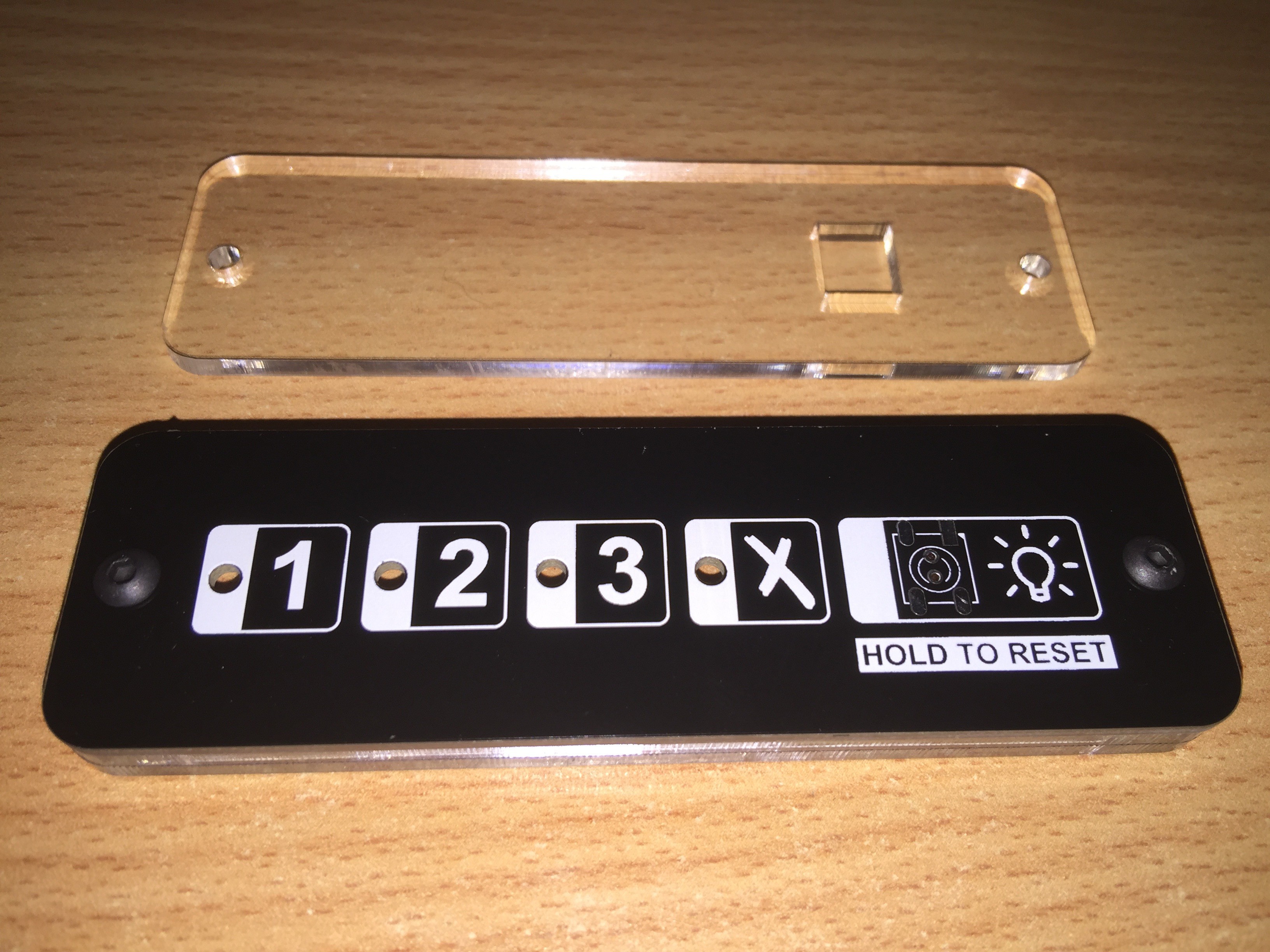
This project is a simple battery operated device that will sit on my desk, bed side table, or wherever. 4 LEDs indicate Day 1, Day 2, Day 3, and Replacement Required. They will be Green, Yellow, Orange, and Red to make it clearer at a glance.
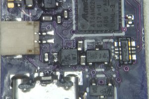
MSP430G2201 was chosen because it was dirt cheap ($0.43 AUD), was low power, and supported a 32.768kHz watch crystal as the external clock crystal. The MSP430G2001 is cheaper again ($0.32) but has less program memory. However, I might not need the extra flash in the 2201 anyway.
I wanted the front panel to be totally clean so I had a nice silk-screen overlay. This meant no vias or through hole components. Some juggling of IO pins used for each LED and the switch meant I could do the whole thing single sided. The pushbutton switch on the front is routed to the back with a couple of vias hidden underneath it.
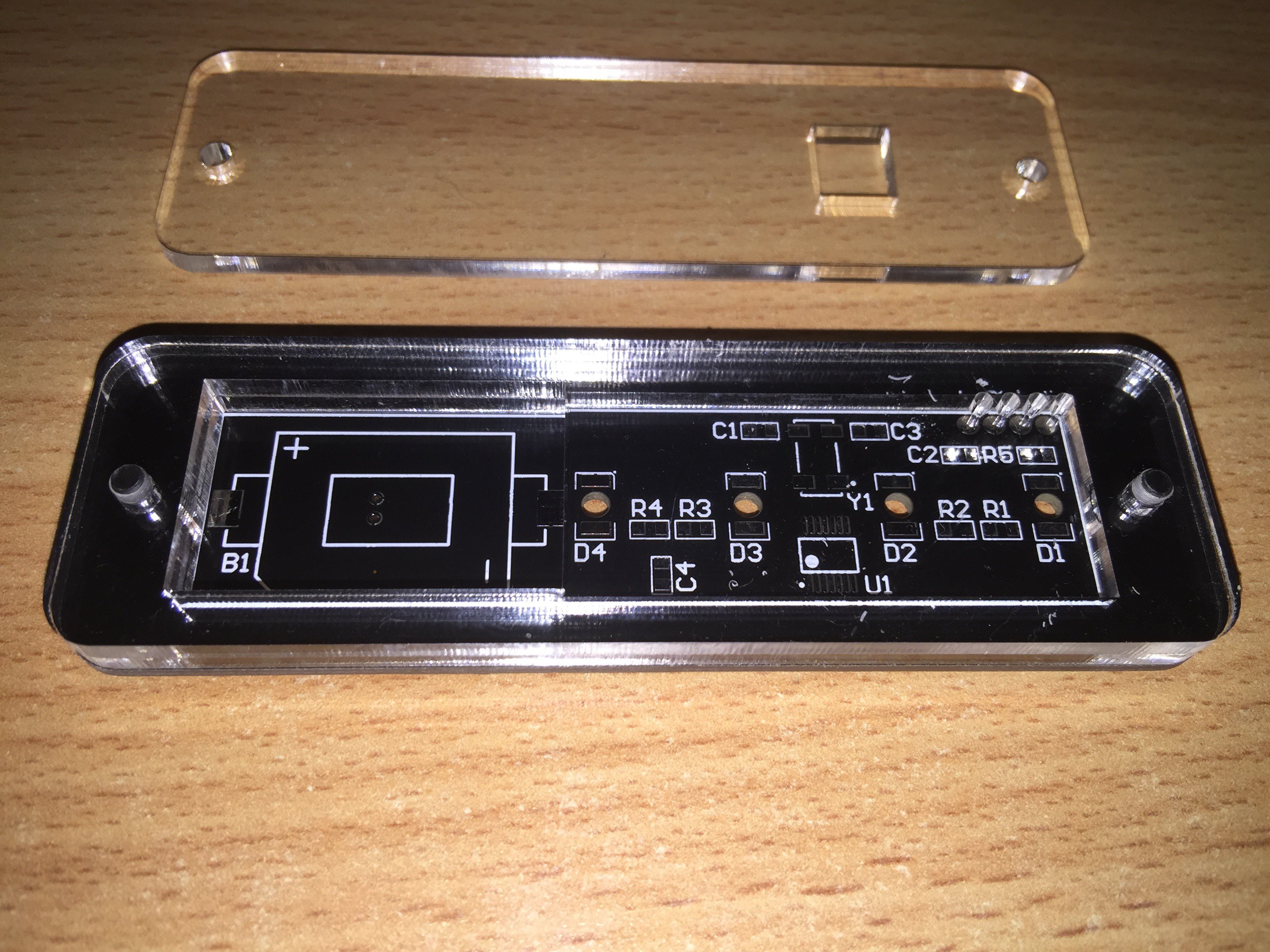
I am having a case laser cut out of acrylic at Elecrow (who are also doing my PCBs). They use 2.8mm acrylic. The case consists of the front piece, a middle spacer, and a back piece. The coin cell holder sits just below the surface of the back piece. The back piece has 2.5mm holes while the rest have 3mm. I'll be using 10mm long button head M3 bolts to hold it together. The 2.5mm holes will be tapped with threads. 2.8mm x 3 = 8.4mm. Add 1.6mm PCB and its 10mm thick. Perfect.
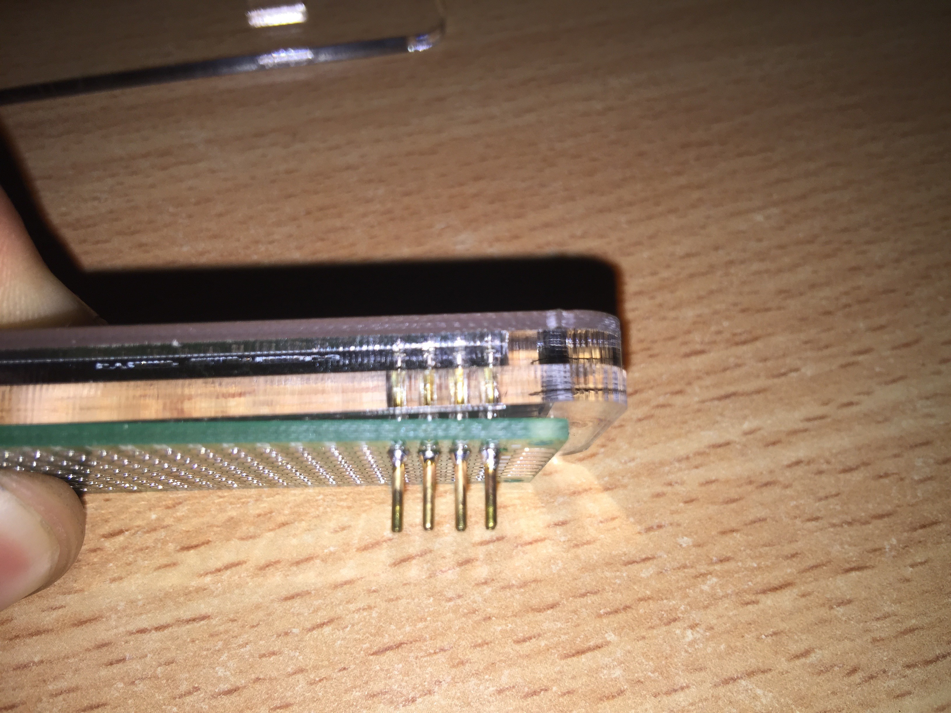
Four small holes in the back panel allow for pogo pins to reach through and make contact with the programming pads. The MSP430 is programmed via SPI BY WIRE. So just Data/Clock/VCC/VSS.
LEDs are OSRAM Reverse Mount Gullwing TOPLED RG series. Not dirt cheap but easy to mount.
 DrYerzinia
 liebman
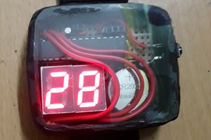
 Brainy.Baboon