 jacksonliam
The other modules I looked at were either in a non friendly package, required too much external circuitry that I might get wrong and is time consuming to solder (AP6210 from cubietruck), were too expensive (Atmel) or tricky to source (SDIO m.2 cards in some tablets). Or didn't support 150Mbps WiFi (ESP8266/ESP8089). Or had questionable or non existent Linux drivers.
The RTL8723BS comes in modules with the part number F23BDSM25-W1 or RL-SM02BS-8723BS. Both appear to have similar pinouts. There does seem to be a module with a differential antenna design which wont work on this PCB so make sure the one you buy has a single antenna pin.
The driver I tested is here (there's also one in the nextthing CHIP repo) https://github.com/hadess/rtl8723bs
The board also includes a pinout for a GPIO 3.5mm audio connector for the Pi zero. Though it might be better to use Bluetooth speakers or headphones as the module is hooked up to the I2S output of the Pi.
The 4 pin header on the board is a UART breakout. The chipsets Bluetooth is connected via the UART but can be disabled to use the UART for something else.


 Andrew Bolin
 Daniel Eisterhold
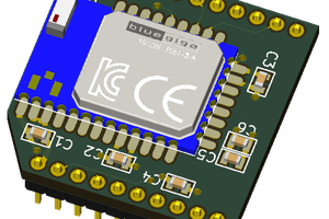
 Clint Stevenson
 Thorsten Jaeger
I see ath10k SDIO support has now been merged into the Linux kernel. https://lwn.net/Articles/706492/ Author references the QCA6584 which is an abgn+ac 2x2:2 design.