 Stephen Holdaway
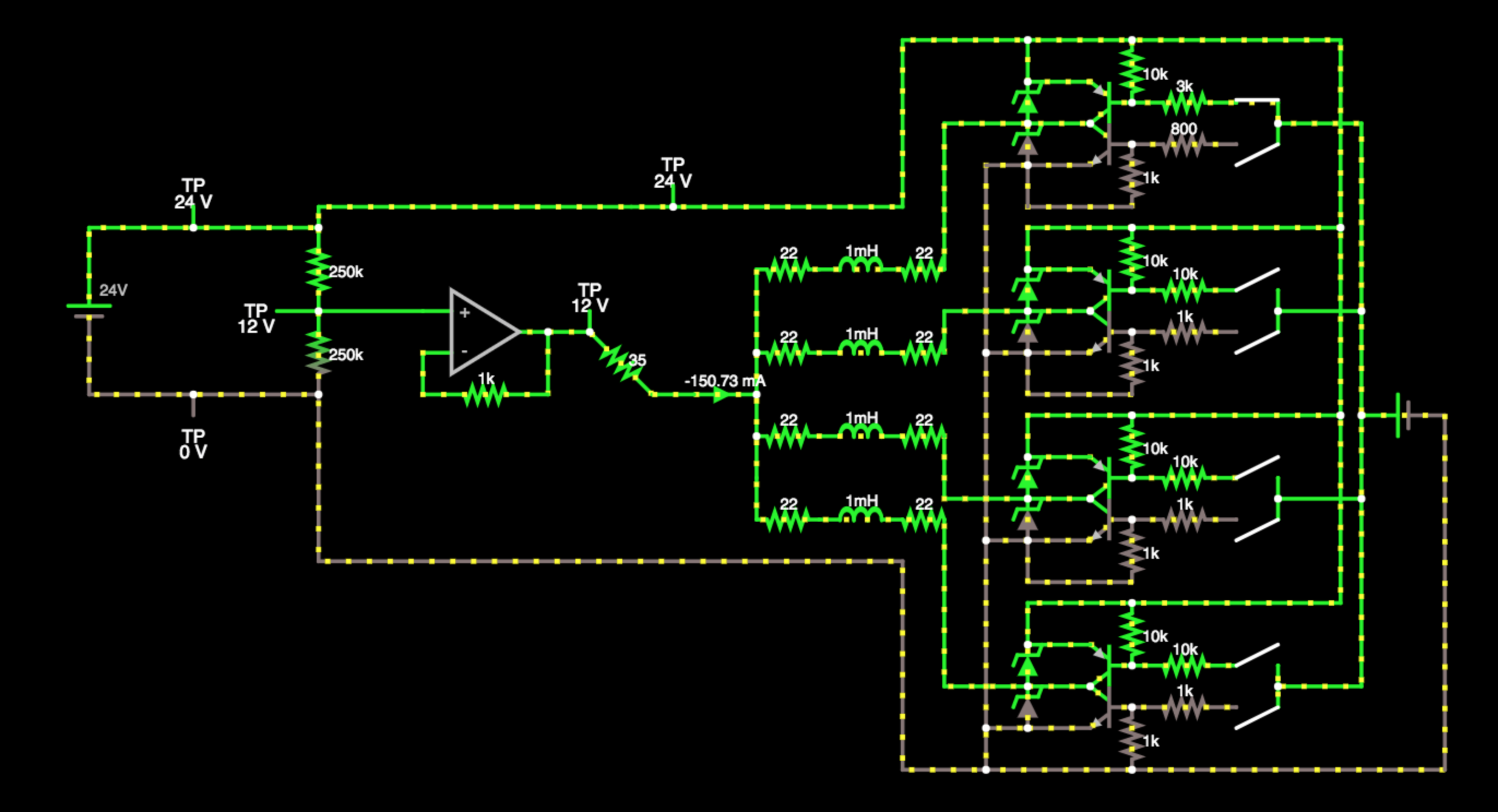
I've been tinkering with this project for about a week so far. Initially I spent a while messing around in Falstad's interactive circuit simulator (above) to figure out how to multiplex and drive these displays.
Segments are switched on and off by powering the appropriate coil briefly in forward and reverse polarity. The datasheet suggests driving the coils at 16V current limited to 350mA. In bench tests the segments flip from about 9V up, though the field generated is a little weak under 12V.
In the interest of lowering component count, I was curious if I could pull off a driver using half bridges, similar to a push-pull amplifier. Bi-directional driving is often done with H-bridges, but my curiosity got the better of me.
The first pass on the schematic boosts the 5V USB supply to 24V and splits it to a common 12V for the segments. There's a pair of transistors in a push/pull configuration for each segment, attached to all digits. The digits are selected by enabling a PhotoMOS solid-state relay that connects them to the 12V rail.
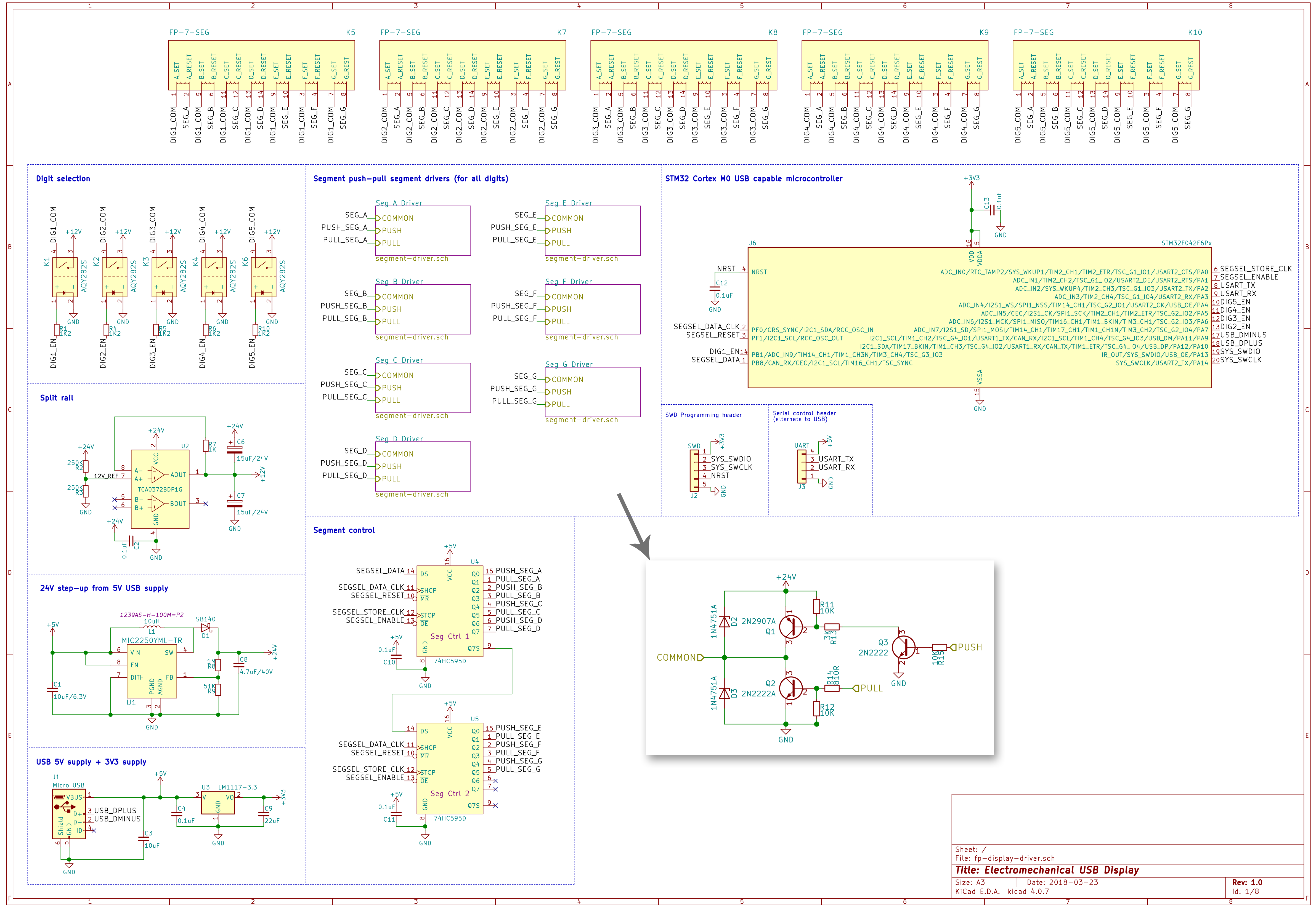
There's a few disadvantages with this split-rail design however:
- Need to generate twice the coil drive voltage: the voltage across the display coils will only ever be half of the total generated in either direction. Maximum ratings of components start to become a problem around 30V.
- Larger and more expensive components: the op amp splitting the rail needs to sink and source around 500mA, which I haven't found in a package smaller than a DIP-4. The PhotoMOS solid state relays work, but are much more expensive than a few SOT-23 transistors per digit.
This split rail supply works fine in theory, but the real-world components to make it work with 300-500mA pulsed currents are excessively expensive. Using a dual supply to get +15V and -15V at the required currents has similar issues with cost, though it removes the need for a big op amp.
Other updates
I've roughed out an enclosure design to get an idea of PCB size:
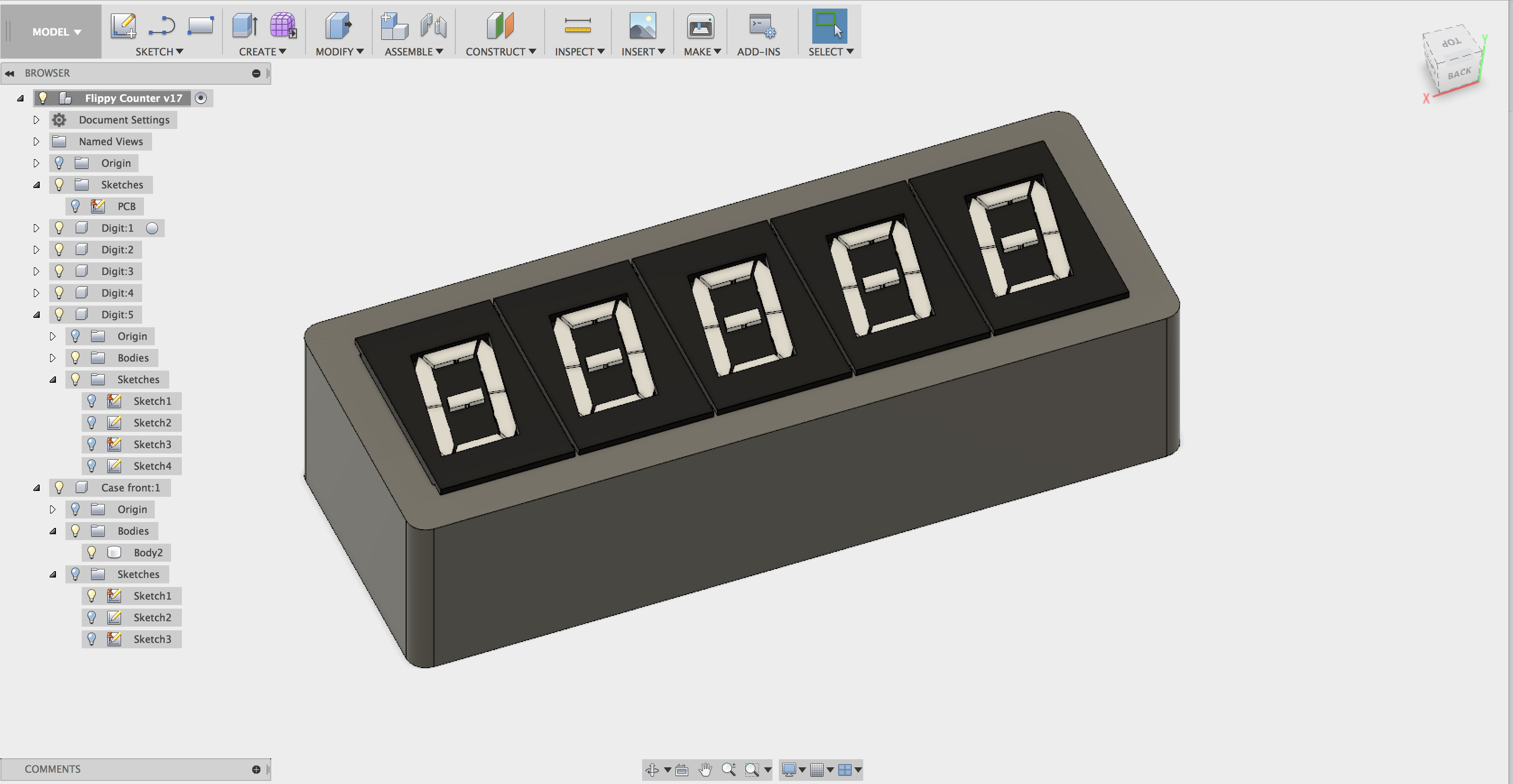
PCB layout is on hold until I've revised the schematic, but I started on this. Needs some thought about mounting.
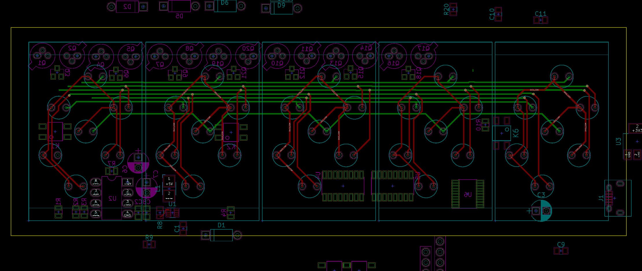
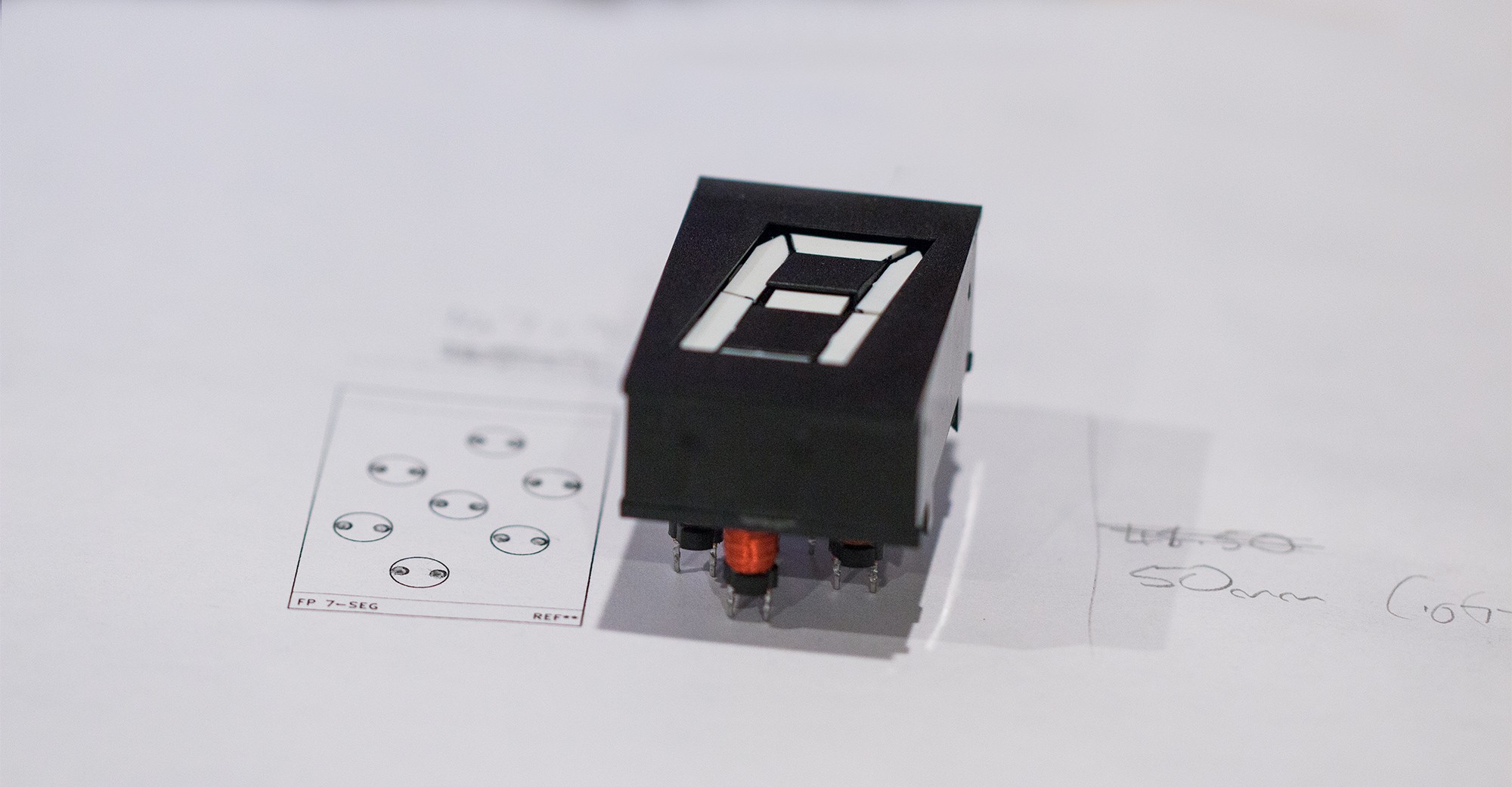
Tested the footprint for the displays - it fits well:
Discussions
Become a Hackaday.io Member
Create an account to leave a comment. Already have an account? Log In.