 Andrey
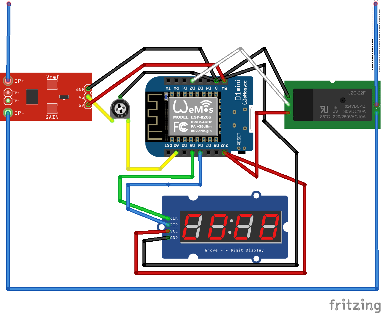
I added a fritzing diagram of how I have connected the different components to the NodeMCU. The thing worth mentioning is the 10kΩ potentiometer that I used to reduce the 5V output from the ACS712 current sensor. I figured out that the NodeMCU actually reads up to 3.3.V on the analog input pin and not the 1.1V as per the specification of the ESP8266. I encountered another problem with analog input read. When there was no current to read from the ACS712 the readings from the analog pin were too erratic. I solved this in code by calculating the frequency of the current readings and only taking it in account if it was 50Hz. Please, feel free to ask me anything if the diagram is not clear to you.
Discussions
Become a Hackaday.io Member
Create an account to leave a comment. Already have an account? Log In.