 zakqwy
It's a hacking project, right? That means unexpected last-minute changes! Also, lots of updates that lack significant progress. Oh well, one step at a time.
First of all, I apologize for the quality of these pictures. My cheap but effective camera seems to have a dead battery (I forget to charge it on occasion), so these were taken with my phone. I wasn't terribly careful so they might be somewhat blurry. I'll let the photos and italic captions tell the story.
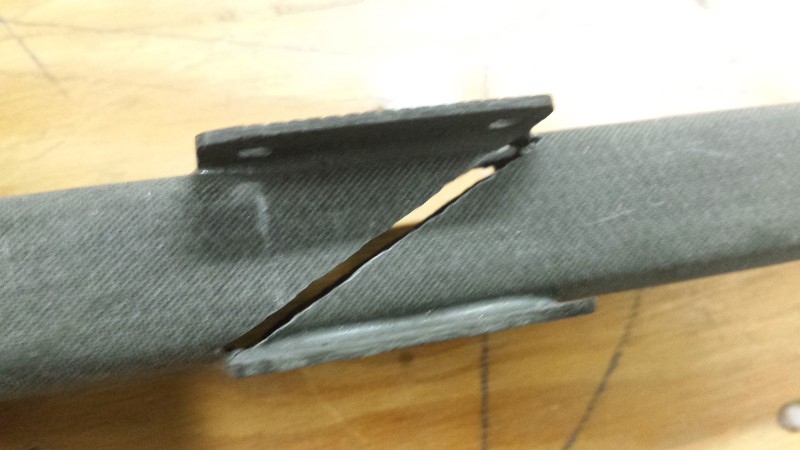
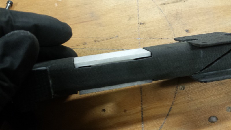
I used the Dremel with a skinny diamond bit to carve a pair of diagonal slots under the motor mount plates as per the CAD drawing; however, I ran to some issues with getting the 1.6mm CFRP plate to slide into the slot cleanly. It fits tightly for most of the length of the slot, but I had some issues at either end--it's tough to get the bit in without buzzing through the motor mount plate. Worse, even after a fair amount of work with a thin metal hacksaw blade (now extremely dull), I realized that the CFRP plate was quite close to the outlet of one of the cooling ducts. I don't want to create an unnecessary pressure drop. Then it hit me... I don't need the slot at all. Or the CFRP insert. I don't need to divide the exhaust from the motors between the two venturi tubes at all. Man, I wish I'd thought of that before severely compromising the structural integrity of the motor mount. Oh well, nothing a sketchy patch can't fix, right? For testing, I'll probably cover the slots with tape.
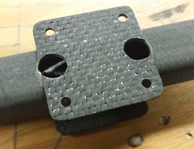
No real drama cutting the vent holes for the motor, although I did almost mark them improperly when mocking everything up with the motors. Rather than further dulling my HSS drill bits I opted to cut these using the diamond bits.
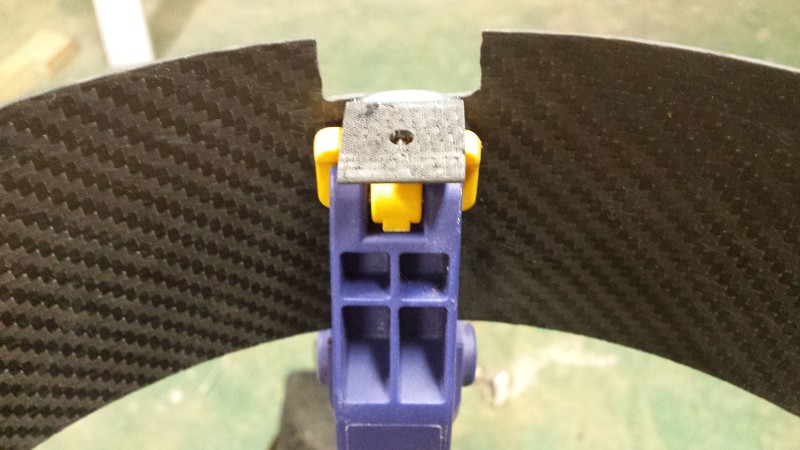
Fitment is right on the money. Yes, CFRP dust tends to get caught in SLS parts, so they look dirty. The vent inserts stay in pretty well so I probably won't glue them in for testing; once I've got everything sorted I might epoxy them and use some silicone to make a form-in-place gasket to reduce leakage around the motor connection. Or likely not.
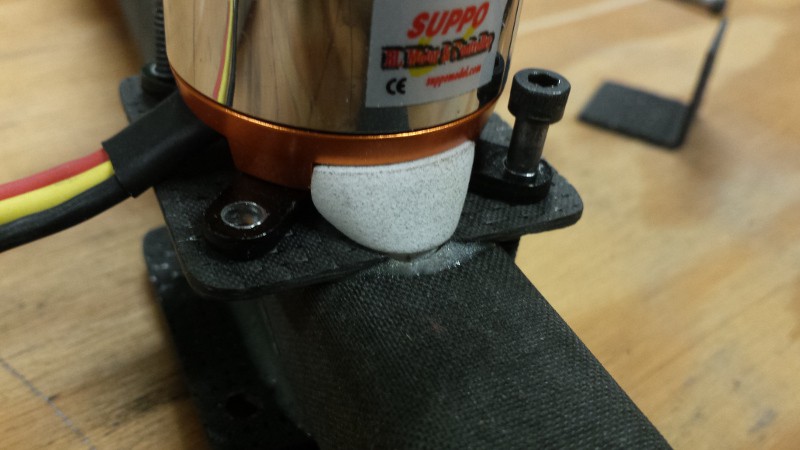
This cut went fairly well. Again, I used diamond rotary bits for everything and checked fitment several times.
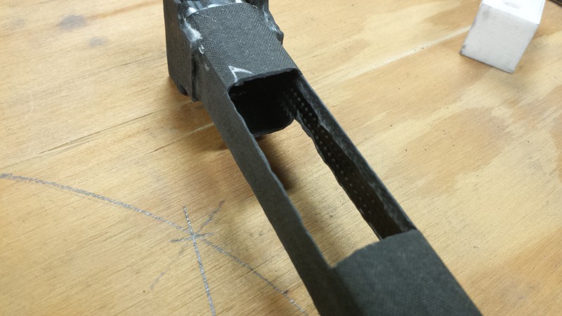
Uh oh! Yup, you guessed it--I wasn't able to maintain a sharp edge around the curved portion of the square tube and ended up losing a few millimeters of height. The air gap would be a serious issue, unfortunately. I was afraid this would happen, but it's a good excuse to install a few reinforcing strips that should probably be there anyway.
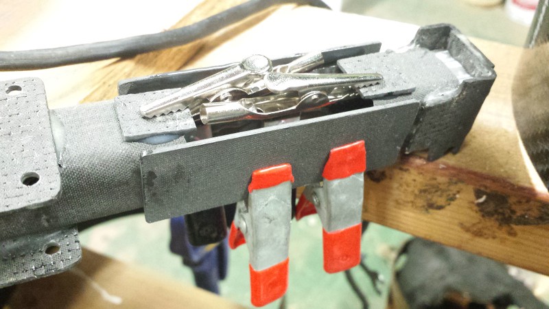
Several chunks of CFRP getting glued a clamped here: two side pieces for reinforcement and air sealing (I'll use RTV or something to ensure a good seal) and two tiny scraps to prevent the venturi from falling through. I thought about leaving a tab when I cut the CFRP, but I didn't really have a good way to interface that tab with the venturi insert without some modification of the SLS parts. Man, the rapid prototyping department should really spend more time communicating with the composites department.
I had the glue out, so I also glued a few tabs that I'd cut earlier onto the fan shrouds. I'll need to drill matching holes in the motor mount to hold these on during testing.
Discussions
Become a Hackaday.io Member
Create an account to leave a comment. Already have an account? Log In.