 zakqwy
Had an offline discussion with a good friend (and extremely talented aerospace engineer):
[Friend]
Here's my two cents: I'd go with your venturi design. I think you'll have better luck pulling air through the motor in the same direction the propeller is pushing the air (if only for the top motor). The nozzles you had pictured in your post looked cool, but I don't think they'll help you too much because your flow field probably looks something like this: https://forum.solidworks.com/servlet/JiveServlet/showImage/2-373006-92361/Untitled.png
From my understanding, those nozzles are meant to have the follow go straight into them (like within a pipe or at the very front of an airplane). Your down-wash is going to be going all kinds of unpredictable directions. I'd just leave open slots and let the high velocity (low pressure) air go through the slots pulling the air near the motor through, helping to cool it. How big should the slots be? Maybe 1/3 the radius? There's a trade-off there. Too big and you lose structural strength. Too small and you'll get no cooling air flowing. There's also going to be some unquantifiable lift penalty. I'm not sure if lift is already an issue for GimbalBot or not.
You were right about the velocity increasing on the post-propeller flow as you go out radially. I think it would look more like part (b) of this picture though: http://energyresources.asmedigitalcollection.asme.org/data/Journals/JERTD2/26499/009104j.1.jpeg
The twist on airplane propellers is usually set based on the maximum lift to drag ratio for a certain flight speed and/or throttle setting; not to achieve a uniform down-wash velocity profile like pointyointment implied. Not sure how much thought was put in to your propeller twist by the manufacturer, but it's probably pretty good.
Good luck Zach! I'm excited to watch how GimbalBot progresses!
[Zach]
Thanks for your comments. I share the concern about structural integrity; I've got a lot of extra CFRP plate I can glue on to the sides of the motor mount if necessary which should help improve stiffness. We'll see how cleanly I can cut slots in the motor mount tube.
I think I'll probably put nozzles in either way; to be clear, when I say 'nozzles' I'm referring to the small duct that interfaces between the bottom of the motor and the top of the CFRP motor mount: https://cdn.hackaday.io/images/8226951407893975604.png
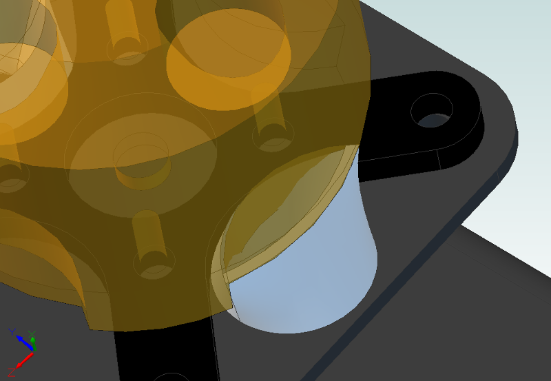
I suspect not sealing that gap could give me trouble by sucking in air below the motor, reducing the flow past the stator.
Agreed on the unpredictable down-wash. I'm guessing the flow below the propeller will be quite turbulent and also have a fair degree of 'twist'. Think I could design a venturi nozzle whose inlet is at an angle (say 30 degrees or so) to ideally capture the flow stream a bit more head-on?
Here's a thought: I could design a few different venturis and see which (if any) has the greatest effect on motor temperature, and run some baseline tests with the ducts closed and completely open. Fortunately, the parts I'm looking to print are small enough that they'll be cheap to rapid prototype.
Mind if I post our discussion on the comments section? I try to do that when I have offline conversations with folks, mostly so I can keep everything in once place (and hopefully so other people can contribute too).
Zach
[Friend]
No amount of speculation beats a test. I think trying some different venturis is a great idea.
Feel free to post our conversation.
[Log]
I'm having some issues with Cubify Design producing *.stl files; once I get that sorted, I'll send the nozzles and a few different venturi designs off for rapid prototyping.
Discussions
Become a Hackaday.io Member
Create an account to leave a comment. Already have an account? Log In.