 Alberto
-
1Step 1
This is an illustrated guide on how to assembly a module (v2) for the Dtto Modular Robot.
![]()
In the project files you will find the following documents:
- Bill of Materials
- List of 3D Printed Parts
- Schematics
- STL files for printing
You will find all the documents also on:
https://github.com/otrebla333/Dtto-Modular-Robot
Components:
Quantity
Description
22
3D Printed Parts
1
Arduino Nano v3.0
1
HC-05 Bluetooth Module
1
NRF24L01+ Wireless Transceiver
24
Neodimium Disk Magnets (4x3mm)
2
TowerPro MG92B Servomotor
3
TowerPro SG90 Servomotor
2
Li-Po Battery 3,7V 600mAh 25C
1
LM317 Voltage Regulator
1
Mini Switch
1
WS2812 RGB LED
40
M1.7x4mm Self Tapper Screw
1
330 Ohms Resistor
1
1200 Ohms Resistor
4
520 Ohms Resistor
3
Small Rubber Band (dental braces)
This tutorial will show how to assembly a fully working Dtto Modular Robot module. We strongly recommend you to have close by a rasp (nail file, emery board, sandpaper) and a set of precision blades.
First of all, we need to print all the parts of the robot. For this type of project, whe think that ABS plastic it’s better because it is more machinable than others. The .stl files are available in the links in the first page. You also have a link to a pdf file detailing how many parts we need, each Part Nº and some details (List of 3D Printed Parts). We will be using the Part Nº to identify the parts. We also need the schematics file to check the connections.
Once we have all our parts printed, all supports removed and carefully sanded, we can proceed to the assembly of the module.
Note: In this tutorial we won’t be assembling the IR detection system. This feature will be available as soon as possible.
We do not take any responsibility and we are not liable for anything occurred while assembling and working with this modular robot. :)
-
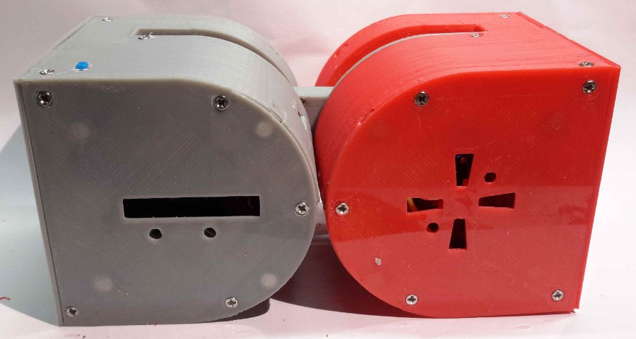
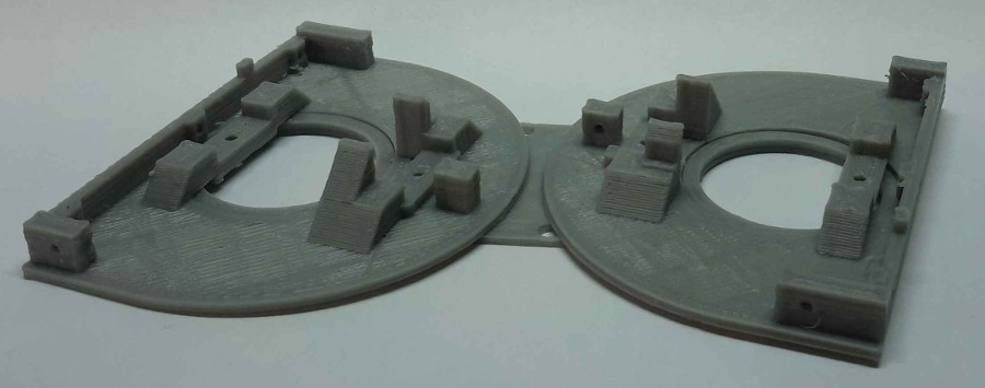
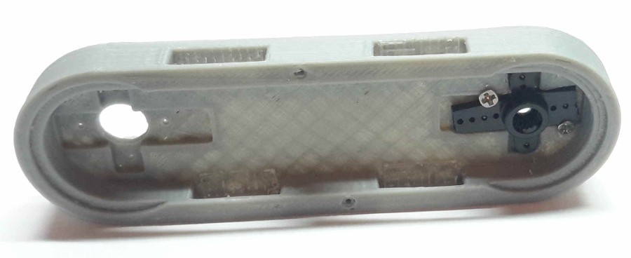
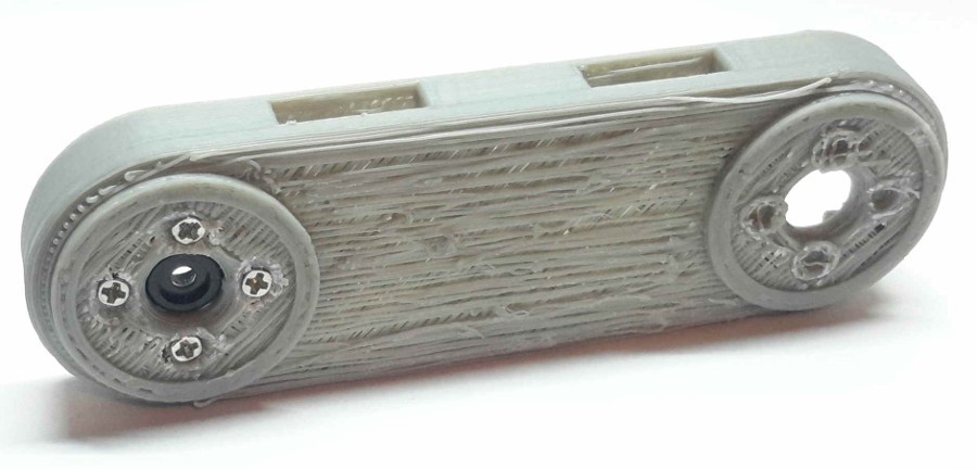
2Step 2
We need:
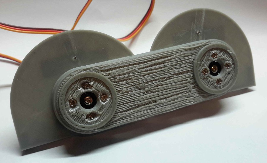
- 2 x Part 004-1
- 1 x Part 011-1
First of all, we have to ensure these 3 parts fit perfectly. It is very important that the 004-1 Parts rotate freely around the center. The easier they rotate, the less energy is lost in friction -> the robot moves better.
![]()
![]()
-
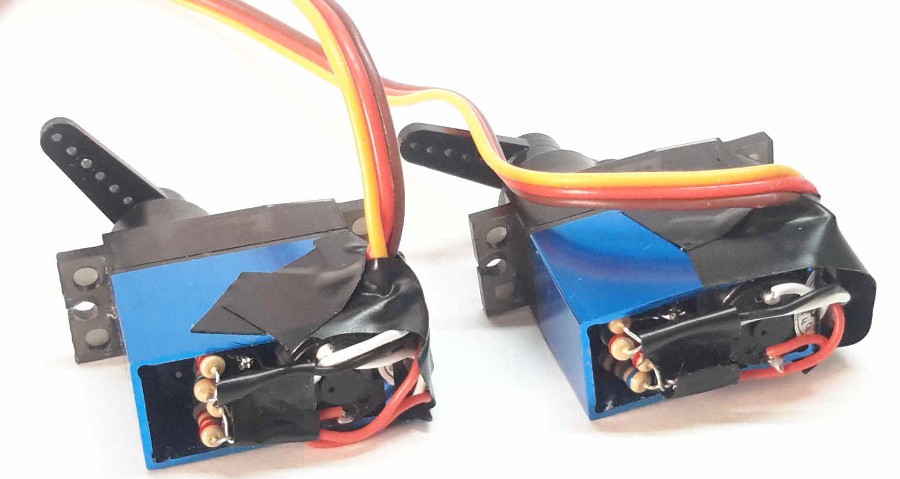
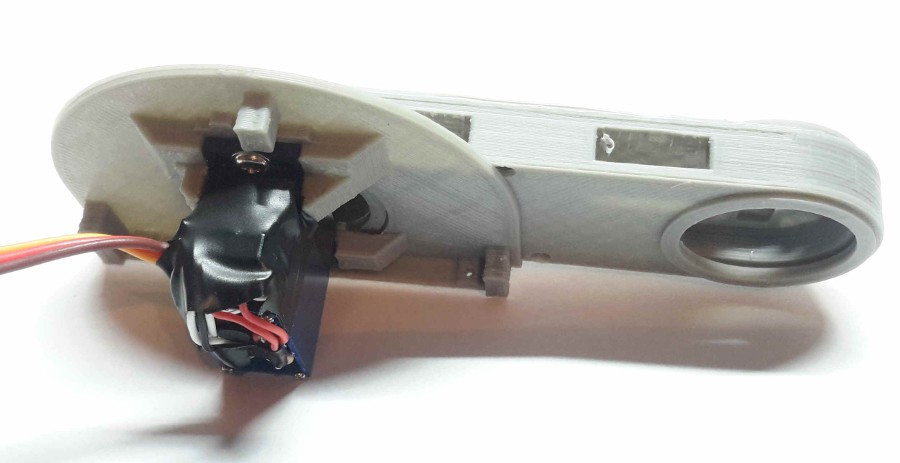
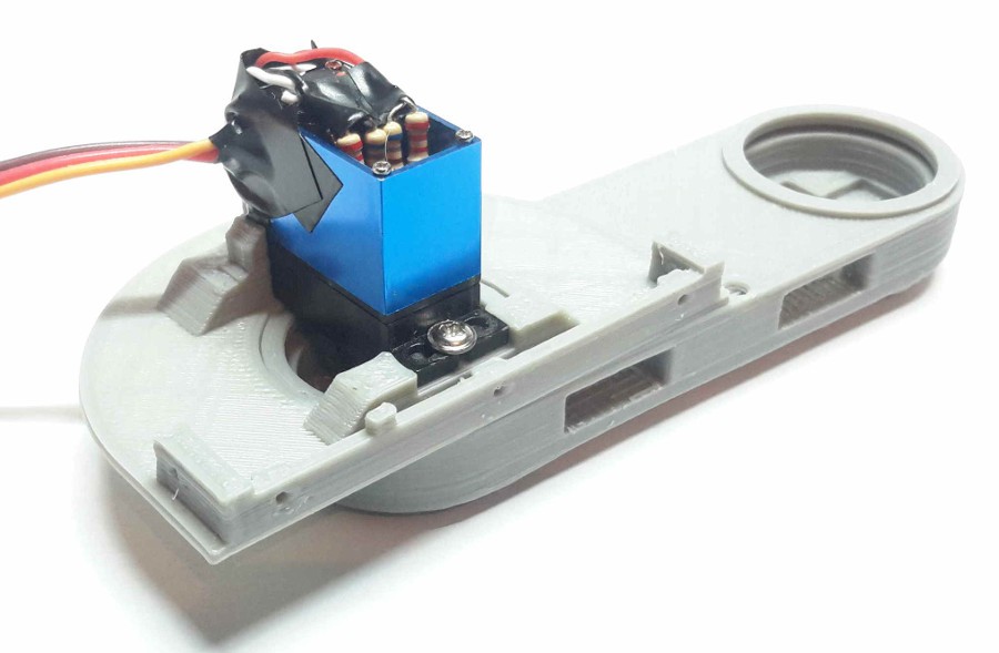
3Step 3
We need:
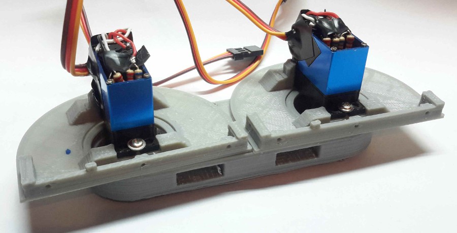
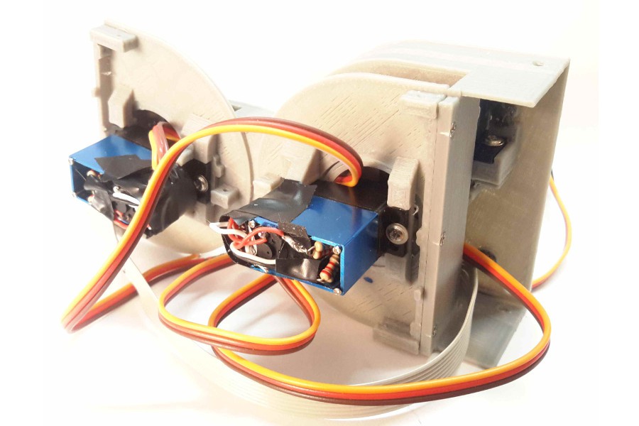
- 2 x MG92B Servomotor
- 4 x 520 Ohms Resistor
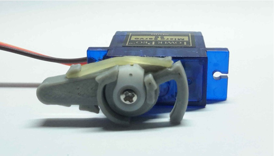
The second thing to do is to adapt the MG92B Servomotors to turn the full 180 Degrees. The method we used was to add a couple resistors to each servo control circuit:
- Take apart the back cover of the servomotor (4 screws).
- Carefully separate the control circuit from the inside. The potentiometer is located under the circuit (it may be covered by a black film). Once you can access the 3 pins of the potentiometer,you have to unsolder the first and the third cable (not the center one). Then, you have to solder a 520Ohms resistor to each of these two pins, and then solder the cable to the resistor. You can find tutorials on how to modify servomotors (search: Modify servo 180 degree), but it’s important you use the 520 Ohms resistors (in the pictures we used one 680 and one 2200 Ohms resistors in parallel to get the 520 Ohms).
- The control circuit does not fit the casing anymore, so we are going to stick it to the side of the metal case (see pictures). Protect the circuit from short-circuits with some tape on both sides.
- Repeat the procedure for the other servomotor
![]()
![]()
-
4Step 4
We need:
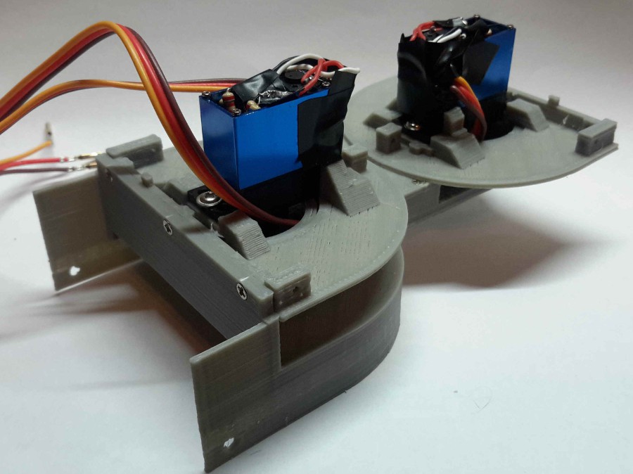
- 2 x Part 004-1
- 2 x MG92B Servomotors (step 3)
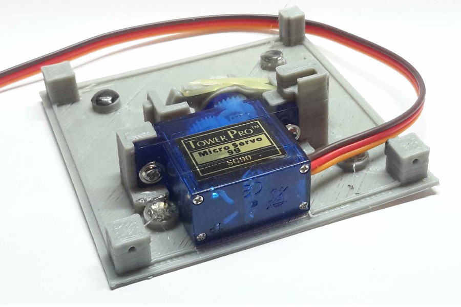
In this step we are going to fix the motors to the printed parts. The motor should fit correctly. We can use the screws that come with the motor, but we will have to cut them to the right length.
![]()
-
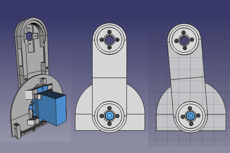
5Step 5
We need:
- 1 x Part 011-1
- 1 x Part 012-1
- 2 x Servo Arm (Cross)
Now we are going to fix the servo arms to the 3D printed part. This step is very important because we have to ensure that the servomotor is centered. If it is not centered, once assembled, the module motor won’t be able to rotate all the way.
The next image illustrates the result. When the servo is set to 90º (servo.write(90)), the relative position of the parts should be like in the center picture. If the position is slightly deviated, like in the picture on the right, we will have to center the part.
![]()
If we set the servo to 90º and get a deviated position like in the picture on the right, we will have to un-center the servo arm, like in the following picture:
![]()
![]()
This is a critical
part, so be sure to get a well centered configuration. Once we get a
well centered part, we have to be completely sure that we got a
correct configuration. We can connect the two parts and test the
rotation with the “sweep” example in arduino IDE.
![]()
![]()
Once we finish with one servomotor, we can proceed to fix the other one.
![]()
![]()
At this moment, the module does not have a male or female part assigned. We will choose one half and we will name it Male. The other will be the Female half. Then, we have to put the cables of the female motor through the hole in the central part, to the male part. You have to ensure that the cables allow a free rotation of the parts.
![]()
-
6Step 6
We need:
- 1 x Part 003-1
Now we will start to assembly the male half of the module. First of all we have to ensure that the hole in the part 003-1 fits with the previously assembled part 012-1. Once sanded, we can attach the part 003-1 to the part 004-1 using 3 screws.
![]()
-
7Step 7
We need:
- 1 x Part 005-1
- 1 x Part 007-1
- 1 x Part 009-1
- 12 x Neodymium Magnets
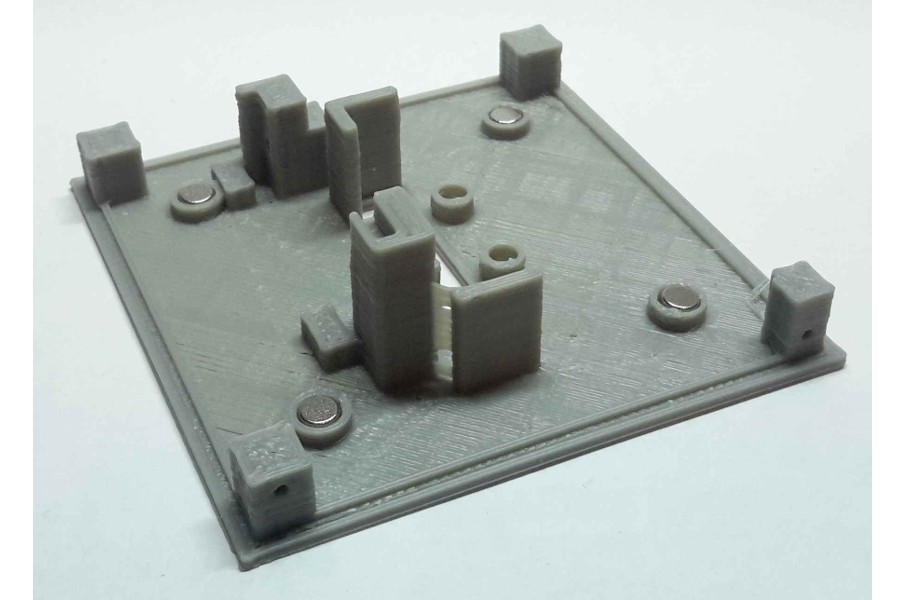
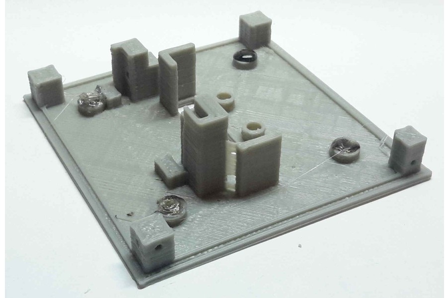
In this step we will put the magnets on the male parts. It is very important to put all the magnets in the male part with the north pole facing the inside of the module. We put the magnets in the holes, and then we put a drop of glue sticking it to the part. For this procedure, we like to use hot melt glue.
![]()
![]()
We repeat the procedure for the 3 parts.
![]()
-
8Step 8
We need:
- 1 x Part 006-1
- 1 x Part 008-1
- 1 x Part 010-1
- 12 x Neodymium Magnets
As we did in the previous step, we will put the magnets in the female parts. Now, remember to put all magnets with the north pole facing the outside of the module. If we do this correctly, the male parts won’t stick between them, but a male and a female part will be magnetically attracted.
-
9Step 9
We need:
- 3 x SG90 Servomotors
- 3 x Part 013-1
- 3 x Part 014-1
- 3 x Small Rubber Band (dental braces)
In this step we will prepare the coupling mechanism that holds the modules of the robot together. We first insert the servo arm (previosly cutted as in the pic) through the two printed parts. We have to ensure that these parts rotate freely around the servo arm. We put the servo in the 90º position (servo.write(90)), and then we screw the parts like in the picture, using the screw that came with the servo. Finally, we put the rubber band between the two parts.
![]()
![]()
We repeat the procedure with the 2 SG90 servomotors left.
-
10Step 10
We need:
- 1 x Part 005-1 (step 7)
- 1 x Part 007-1 (step 7)
- 1 x Part 009-1 (step 7)
In this step we will fix the servos that form the coupling mechanism to the printed parts. First we will insert the servo in the correct position. Then, using the 2 screws that came with the servo, we will fix it to the part.
![]()
![]()
We will repeat the procedure for the 2 parts left.
Dtto - Explorer Modular Robot
Modular self-reconfigurable robot, focused on all-terrain search and rescue operations using bio-inspired locomotion mechanisms


Discussions
Become a Hackaday.io Member
Create an account to leave a comment. Already have an account? Log In.
Thermoglue is very bad for magnets. It is possible to damage magnetic properties.
Are you sure? yes | no
Ya know, I thought you were crazy. I haven't worked much with magnets. But after researching on K & J Magnetics, you are right! N52 will start to demagnetize at just 176F (80C)! GREAT to know! Thanks for posting! I learned something today! :)
Are you sure? yes | no
what is the purpose of this rubber band? just curious. I would be nice to have a video showing tht lock working. thanks
Are you sure? yes | no