 Eric Hertz
It's been some time... I don't recall what LVMDS stands for anymore...
LVDS = Low-Voltage Differential-Signalling...
And the M...? Multi?
Some theorizing was presented in previous logs (long ago), here's my attempt at trying to remind myself what I was thinking.
-------------
Anyways, here's anaQuad revisited:
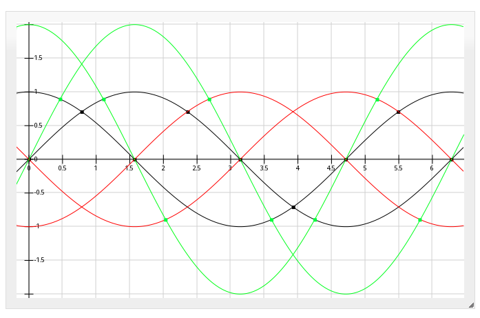
There are two sine-waves, with a 90-degree phase-shift between 'em. (the two blue lines). These are, e.g. the outputs of the two Quadrature signals of an optical-encoder.
anaQuad, again, increases the resolution of the encoders by looking at crossovers between various multiples of the two input signals. By *inverting* the two input-signals (red), we can detect 8 positions (8 cross-overs) per full-cycle (the blue dots). (This resolution is twice as high as could be detected with digital quadrature signals).
By multiplying the input-signals by ~2, we can double the resolution to 16 positions (the green dots). The resolution can be further-increased by adding more [and more complicated] multiples of the two input-signals, but let's ignore all these for a second and just look at the red and blue waves.
The red and blue waveforms give 8 positions per full cycle. That's 4 positions per half-cycle, using two quadrature signals.
That's for increasing the resolution of a quadrature [optical] encoder with analog output.
-----------------
Imagine, now, if these crossovers represented data-bits in a serial-data-stream...
-------------------------
First some background...
Here's an "eye diagram" for a regular ol' serial-data-stream (e.g. RS-232)

The waveforms forming the "eye" are numerous bits of a data-stream overlayed atop each other.
 (
(When the bit in the center is high, and the two surrounding it are low (#7, above), you'll see a full-sine-wave, starting low on the left, rising to the top of the "eye," and ending low on the right. (If the baud-rate is *really slow* compared to the rise/fall times, it'll look more like a square-wave... as one might expect of a digital signal. For a high-speed serial data-stream, the rise-times and fall-times are almost as long as the high-level and low-level bits, making the waveform more of a sine-wave.)
Similarly, when the bit in the center is low, and the two surrounding it are high (#5), you'll see the same half-sine-wave flipped upside-down.
When three bits are high (#4), you get the top line straight across. Three low, straight across the bottom (#2)... And several other combinations (two bits high, one bit low (#8), and so-forth).
So the eye-diagram shows many bit-patterns overlapping. One might say the center of the "eye" is sampled by the input of the receiving shift-register.
-----------------------
Now, for a *differential* serial data signal, we'd see a similar diagram; for every high-bit on one wire, the other wire sends a simultaneous low bit, and vice-versa. It's symmetrical across the horizontal line bisecting the eye (wee!).
Generally, the receiver might be e.g. a comparator connected to those two opposite-valued signals. When one signal is higher than the other, the output of the comparator is 1, when the other signal is higher, the output is 0.
The bit-value is, essentially, determined at the *time of crossover* between the two input-signals. (Though, technically, most LVDS receivers *sample* the bit-value in the middle of the "eye").
--------------
Now let's go back to anaQuad...
anaQuad works by looking at the *crossover* of two signals, much like differential-signals (LVDS). But, does-so between not only the input-signal (blue) and its inverse (red), but also a second input-signal and its inverse (the second blue and red pair, respectively)... (as well as multiples thereof (green), which I'm ignoring for now).
By transmitting two signals, in quadrature (the two blue waveforms), at the same frequency as, say, an LVDS signal, we can determine *four* different crossover values (the blue dots) in a single "eye" (half-sine-wave) (ignoring, again, the green 2x signal).
Thus, by paying attention to the *crossovers* (the blue dots), two parallel anaQuad-serial signals could transmit *twice* as much information in the same amount of time as two parallel LVDS signals at the same frequency and same electrical characteristics (which could only transmit one "eye," or one *bit*, per channel, in that time. Two bits, for two two-wire LVDS channels, 4 bits for one four-wire differential-anaQuad-serial channel).
AND, that's only if you look at the original signal and its inverse. Including a 2x multiple would allow for 4x the data-rate. The 2x signals needn't be sent on another wire, or pair thereof, it can in fact be handled by the receiving-end.
------------
This is different than sending an analog value down a wire and reading back the voltage at the receiver. That method would be highly susceptible to external electrical noise, characteristics of the transmitter, the wire, and more.
To measure an analog *voltage*, like that, one typically uses an ADC, and detects whether the voltage is higher than some threshold and lower than another. In the case of LVDS, signals are specified at +/- 0.1V, so to measure 4 analog values in that range would require precision/accuracy of 0.05V. At these levels, any number of factors could cause misread values; from external noise, to resistance in long wires, a 0.05V ripple in the transmitter's supply-voltage, a 0.05V difference between the receiver's ground and the transmitter's.
Instead, since we're looking for *crossovers*, many of those sources of "noise" are removed. When the transmitter's supply-voltage varies dramatically, so may its output-voltages. But both the transmitted signals' voltages change together, so no crossover occurs, and the received signal is otherwise unimpeded. Likewise with variance in the ground-signal. And, since we're talking about transmitting each of the two quadrature signals as separate *differential* pairs, external noise coupled-into one of the wires in a pair is equally coupled into the other wire. Since the two are opposite polarities, the noise is canceled out; no unexpected crossovers are detected.
This has the benefit of differential-signals (similar to "balanced" microphone cables), being highly immune to external electrical interference, as well as significantly lower emissions.
----------
So, the idea, then, is to transmit data-bits with quadrature-encoding. E.G. thinking about an optical-encoder, a "1" bit could be transmitted by rotating the encoder clockwise one "tick", a "0" bit could be transmitted by rotating the encoder counter-clockwise one "tick".
Using the method of detecting crossovers of multiples of the input-values in anaQuad, a single "tick" could be a fraction of a full cycle, requiring less signal-swing (and therefore less time) for each transmitted bit.
---------
There are a couple ways I see this working. One is described above... clock-wise = 1, ccw=0. Another possibility is to keep the value unchanged, in which case ternary is a possibility.
Another consideration is the potential use of crossovers as clock-data. Using the CW=1, CCW=0 method, there will always be a change in the input signal for every bit. This change, then, could be used to transmit a clock-signal simultaneously down the same wire-pair.
A third consideration is the system's ability to retain a "crossover" value, without bouncing *around* it. This is also a consideration in anaQuad, when used with optical-encoders.
Depending on the implementation, the system could be prone to fast-toggling due to values right *near,* and thus oscillating around, a crossover. This can be easily taken care of by embedding a bit of hysteresis in the system. (and has been described in previous log-entries for encoder-handling).
Imagine, again, the CW=1,CCW=0 scenario... say in the previous bit we've travelled "left" by one blue dot (in the diagram), it travelled CCW, so the last bit was 0. Then for the next bit to be read as "1" it would have to travel *two* blue-dots to the right. (Otherwise, it might be sitting *at* the previous blue-dot, and be mistaken). Now we've reduced our bit-rate by ~1/3rd(?)-1/2, but, again, our bit-rate is already twice the equivalent LVDS signals (with, again, the inherent clocking, which usually requires a separate pair), and we can do 2x scaling of the input to double the bit-rate, again... plausibly more.
Discussions
Become a Hackaday.io Member
Create an account to leave a comment. Already have an account? Log In.
"Thus, two parallel anaQuad signals could transmit *twice* as much information in the same amount of time as two parallel LVDS signals at the same frequency and same electrical characteristics."
But the pigeonhole principle shows that nothing is gained : the entropy remains the same :-)
If you have 1 link that transmits 1b, you can have 2 links that transmit 2 bits. Either with anaquad or 2 separate links.
If I understand, you propose that this method is more immune to noise and might run faster ?
Are you sure? yes | no
No, one anaQuad pair (four wires, using differential-signalling) would transmit twice as much information as two LVDS pairs (four wires). And more, considering the clock-signal is inherently-embedded. The idea, again, being that each LVDS-bit is a half-sine-wave, whereas an anaQuad bit (in the easy-implementation) is 1/8th sine-wave, or even smaller.
In my theorizing, I dunno whether it'd be *more* noise-immune than LVDS, but it'd benefit from the same sources of noise-immunity that LVDS benefits from. The question of noise-immunity may consist of other factors not-yet explored... e.g. LVDS may be relatively immune to effects of signal-<s>bounce</s> <i>reflection</i>, whereas this may be more susceptible to it.
On that note... one of the key-factors of LVDS is ... no...
I was going to go into inter-channel skew... But that's not really the case, at least in the case of FPD-Link (which I've most my LVDS-experience). In the case of FPD-Link, the skew can be no greater than one bit (and, really, needs to be pretty-durn-close to simultaneous). Though, skew is one thing I have yet to analyze... it would likely be a *tremendous* factor in anaQuad-serial. And jitter...? Oy.
The idea of sending the quadrature-data *as* a pair (rather than two differential-pairs) is... questionable. My presumption is that it would be a bad idea... but maybe that's not true. From an *emissions* standpoint, it'd be worse than LVDS, but from a the standpoint of *external-noise-immunity*...? It might be better than having two separate differential-pairs. Hmmm...
Are you sure? yes | no
The pigeonhole principle doesn't apply... This system allows for half- and quarter- pigeons. Though, does not allow for infinitesimal-fractions of pigeons. ;)
Are you sure? yes | no