 Fabien-Chouteau
For this, I will use the great STM32F469 discovery board with a 800x600 LCD and capacitive touch screen. But before that, I have to hack the candy dispenser....
Hacking the dispenser
The first thing to do is to hack the candy dispenser to be able to control the candy delivery system.
The candy dispenser is made of :
- A container for the candies
- A motor that turns a worm gear pushing the candies out of the machine
- An infrared proximity sensor which detects the user’s hand
My goal is to find the signal that commands the motor and insert my system in the middle of it. When the dispenser will try to turn on the motor, it means a hand is detected and I can decide whether or not I actually want to turn on the motor.
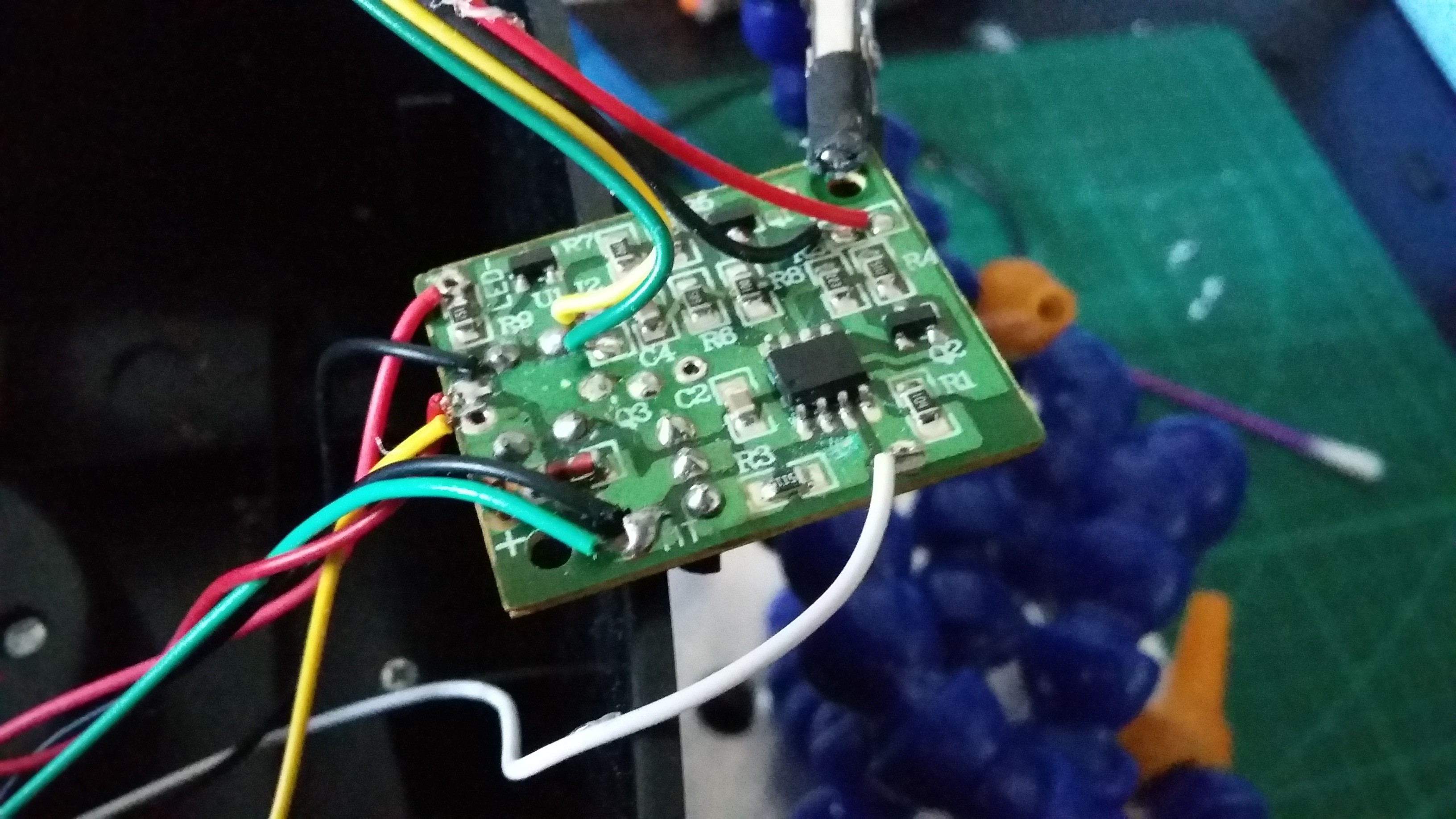
To find the signal controlling the motor, I started by looking at the wire going to the motor and where it lands on the board. It is connected to the center leg of a “big” transistor. Another leg of the transistor is tied to the ground, so the third one must be the signal I am looking for. By following the trace, I see that this signal is connected to an 8 pin IC: it must be the microcontroller driving the machine.
At this point, I have enough info to hack the dispenser, but I want to understand how the detection works and see what the signal is going to look like. So I hook up my logic analyser to each pin of the IC and start recording.
Here are the 3 interesting signals: infrared LED, infrared sensor, and motor control.
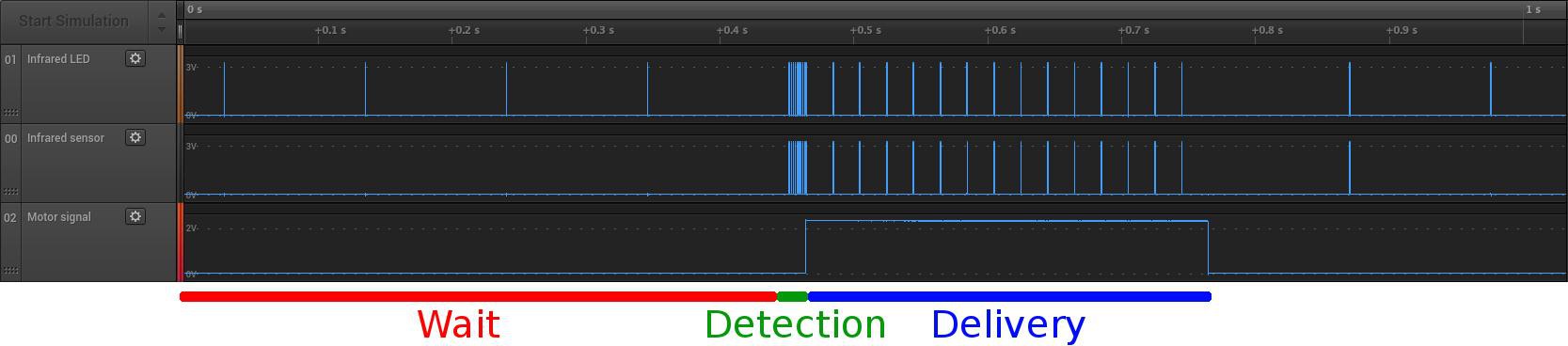
he detection works in 3 phases:
- Wait: The microcontroller is turning on the infra-red LED (signal 01) only 0.2 milliseconds every 100ms.This is to save power as the machine is designed to be battery powered.
- Detection: When something is detected, the MCU will then turn on the infra-red LED 10 times to confirm that there’s actually something in front of the sensor.
- Delivery: The motor is turned on for a maximum of 300ms. During that period the MCU checks every 20ms to see if the hand is still in front of the sensor (signal 03).
This confirms that the signal controlling the motor is where I want to insert my project. This way I let the MCU of the dispenser handle the detection and the false positive.
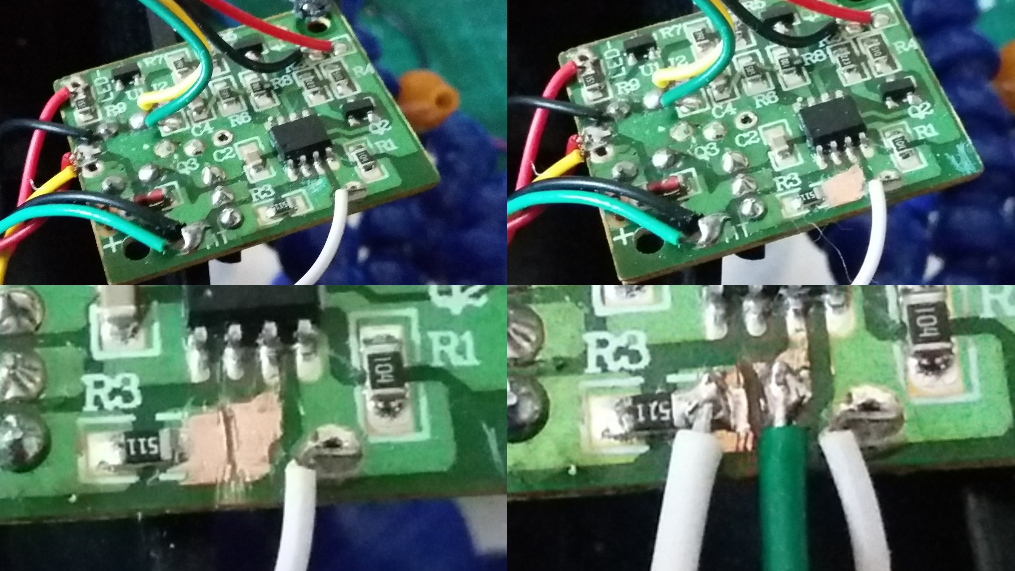
I scratched the solder mask, cut the trace and solder a wire to each side. The green wire is now my detection signal (high when a hand is detected) and the white wire is my motor command.
I ran those two wires with an additional ground wire down to the base of the dispenser and then outside to connect them to the STM32F469 discovery board.
Software
The software side is not that complicated: I use the GPL release of GNAT and the Ravenscar run-time on an ARM Cortex-M on the STM32F469. The green wire coming from the dispenser is connected to a GPIO that will trigger an interrupt, so whenever the software gets an interrupt it means that there’s a hand in front of the sensor. And using another GPIO, I can turn on or off the dispenser motor.
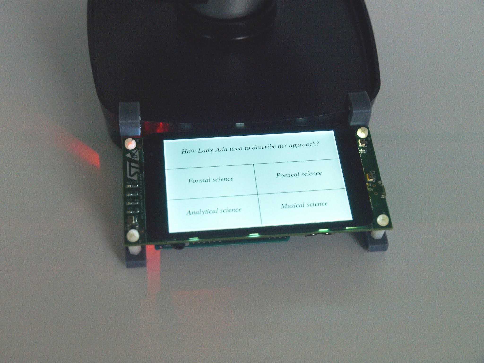
For the GUI, I used one of my toy projects called Giza: it’s a simple graphical tool kit for basic touch screen user interface. The interfaces has two windows. The first window shows the question and there is one button for each of the possible answers. When the player clicks on the wrong answer, another question is displayed after a few seconds; when it’s the right answer, the delivery window is shown. On the delivery window the player can abort by using the “No, thanks” button or put his hand under the sensor and get his candies!
The code is available on GitHub here: https://github.com/Fabien-Chouteau/AMCQ
Now let’s see what happens when I put the candy dispenser back in the kitchen:
See more at: http://blog.adacore.com/make-with-ada-candy-dispenser-with-twist#sthash.XGZt7WOc.dpuf