-
Infrared Light
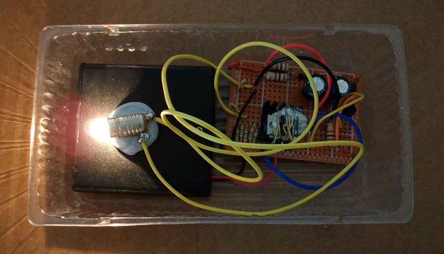
10/02/2020 at 04:08 • 0 commentsThis article shows a simple infra remote control activated light, made with the use of an infra-red receiver IC (integrated circuit). The maximum range can be as long as 20 metres.
![]()
You can see my circuit working in this video:
I designed this circuit after reading those articles:
https://hackaday.io/page/9271-infrared-led
https://www.instructables.com/MOSFET-Touch-Lamp
https://www.instructables.com/Infrared-Lamp
I made my circuit with a traditional 6 V incandescent light bulb. However, you can use an LED light bulb or simply an LED matrix array. Keep in mind that LEDs conduct current in one direction. You can also use a 4.8 V Krypton torch globe:
Step 1: Design the Circuit
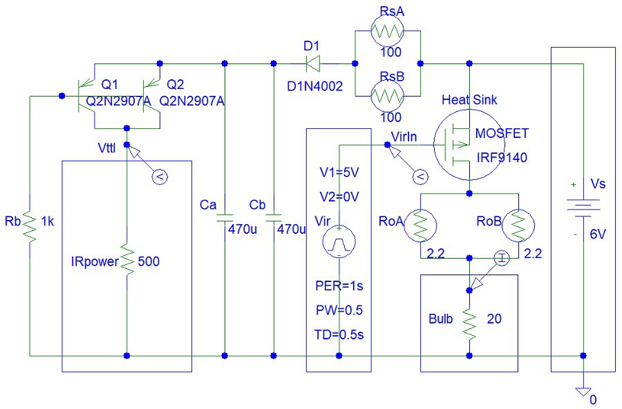
I used the old PSpice software to quickly draw my circuit:
![]()
Nowadays there are IR receivers that can work with a power supply voltage between 2.5 V and 9 V, or even 20 V. Thus the diode and transistor power supply are optional. Also, modern IR receivers have higher bandwidth and can thus receive higher frequency signals.
Step 2: Simulations
The TTL power supply:
![]()
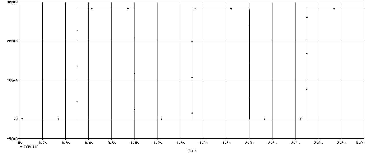
The light bulb is receiving 300 mA current that it needs:
![]()
Step 3: Make the Circuit
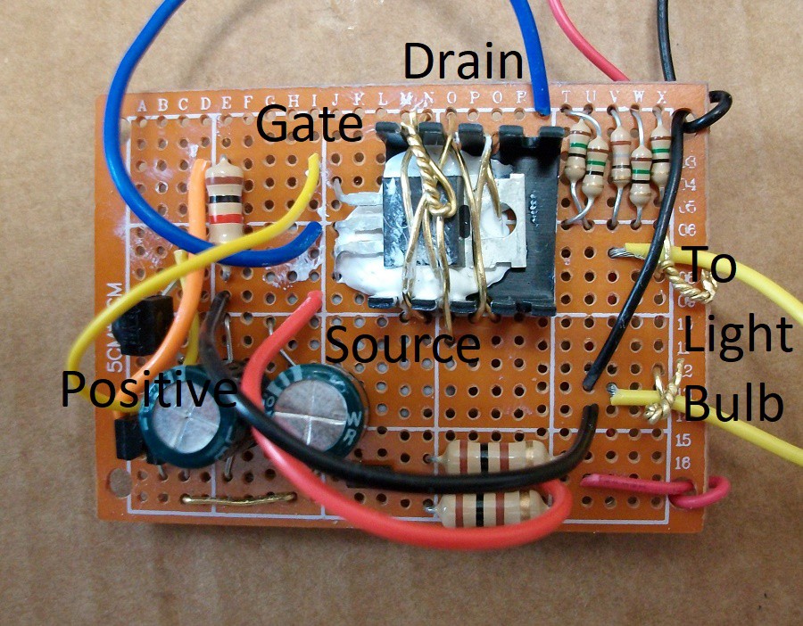
You can see the big MOSFET transistor with attached heat sink:
![]()
I did not have high-power 2.2-ohm high power resistors. Thus I used an alternative. You can replace the 2.2-ohm resistors with a short circuit. However, this will reduce the life time of the MOSFET.
-
Funny Robot
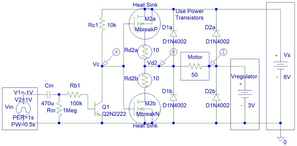
03/30/2020 at 10:15 • 0 commentsThis article presents a simple power transistor inverter and MOSFET motor driver:
![]()
You can see my circuit working in those videos:Second video:
Step 1: Design the Circuit
This is my circuit drawn in the old PSpice software:
![]()
Later I modified the circuit to work with a Zener diode:
![]()
This is a well-known MOSFET motor driver circuit. It is used for MOSFET H-bridge circuits. However, that circuit (H-bridge) might cost more money. You also have to be careful to make sure you do not exceed the maximum gate voltage, the MOSFET input voltage.
You can google MOSFETs on the internet. There is Depletion MOSFET and Enhancement MOSFET. There is a good quote on the internet about the difference between those two types of transistors:
"
- Depletion Type – the transistor requires the Gate-Source voltage, (Vgs) to switch the device “OFF”. The depletion-mode MOSFET is equivalent to a “Normally Closed” switch.
- Enhancement Type – the transistor requires a Gate-Source voltage, (Vgs) to switch the device “ON”. The enhancement-mode MOSFET is equivalent to a “Normally Open” switch.
"
(Source: https://www.electronics-tutorials.ws/transistor/tran_6.html)
I used Enhancement Type MOSFET.
Step 2: Make the Circuit
I used a 3.3 V Zener diode instead of a 4.3 V Zener diode because this is what I had in stock. The use of a voltage regulator will prevent power loss caused by the 100 ohm Rz resistor.
![]()
Step 3: Testing
Testing video:
-
Simple Transistor Modulator
03/30/2020 at 03:15 • 0 commentsThis publication shows how you can make a simple transistor modulator with just one transistor.
The circuits presented in this article are similar to signal sampling circuits because simpel non-linear modulation signal processing is similar to sampling. However, those circuits do not allow linear modulation that was used in AM (Amplitude Modulation) radio.
The period of the sampling signal is 100 us. Therefore the frequency is:
f = 1 / T = 1 / 100 us = 1 / 100 * 1000,000 = 1 * 10,000 = 10 kHz
This is ten times the input frequency of 1 kHz. Thus the signals would not overlap in frequency domain.
Step 1: Design the Circuit
Bipolar Junction Transistor Modulator
![]()
The Q1 transistor acts a switch and saturates when the pulse signal is 1 V.
MOSFET Transistor Modulator
![]()
The MOSFET transistor acts a switch and saturates when the pulse signal is 1 V.
Step 2: Simulations
I used an old PSpice software for simulations:
Bipolar Junction Transistor Modulator
![]()
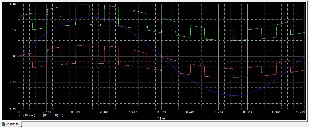
MOSFET Transistor Modulator
![]()
The graph above is showing that the MOSFET transistor is not saturating. There must be something wrong with the MOSFET component model in the PSpice software student edition that I used. Usually MOSFET transistors would have a higher voltage current gain than the value specified in the model.


 Damian Lickindorf
 kodera2t
 Pranav Gulati
 Mark Rehorst
 Jaime García
 Alex Rich
 h4rdc0der
 prateekt
 Jeremy
 Danny Bokma
 RoGeorge
 Stefano Risato
 W. Jason Altice
 scubabear