 Dan O'Shea
-
Getting a BeagleBoard C3 from 2009 to boot at all / boot a 'relatively' modern OS in 2022!
05/08/2022 at 21:57 • 0 commentsSending out this message in a bottle in the hopes of saving other poor souls from days of suffering, and as a reminder note should my future self need it.
- Follow instructions at https://forum.digikey.com/t/debian-getting-started-with-the-beagleboard-xm/12457 to build new MLO and u-boot.img from scratch.
- Follow instructions at https://elinux.org/BeagleBoardNAND#U-Boot_v2011.12_or_newer to erase *all* NAND and write the above MLO and u-boot.img to NAND.
- Download rootfs SD image https://web.archive.org/web/20210224155229/https://rcn-ee.com/rootfs/2020-03-12/microsd/bone-ubuntu-18.04.4-console-armhf-2020-03-12-2gb.img.xz
- Write image to SD using balenaEtcher.
- Make changes on rootfs SD:
- Rename /bbb-uEnv.txt to /uEnv.txt
- Edit /boot/uEnv.txt to replace uname_r=4.19.94-ti-r36 with uname_r=5.4.24-armv7-x20
- Hold down USER button when powering-up.
- Profit!
-
Wifi-Telnet-FPGA-NTSC Drunk Wall Clock
09/08/2021 at 10:20 • 0 commentsWifi-Telnet-FPGA-NTSC Drunk Wall Clock!
![]()
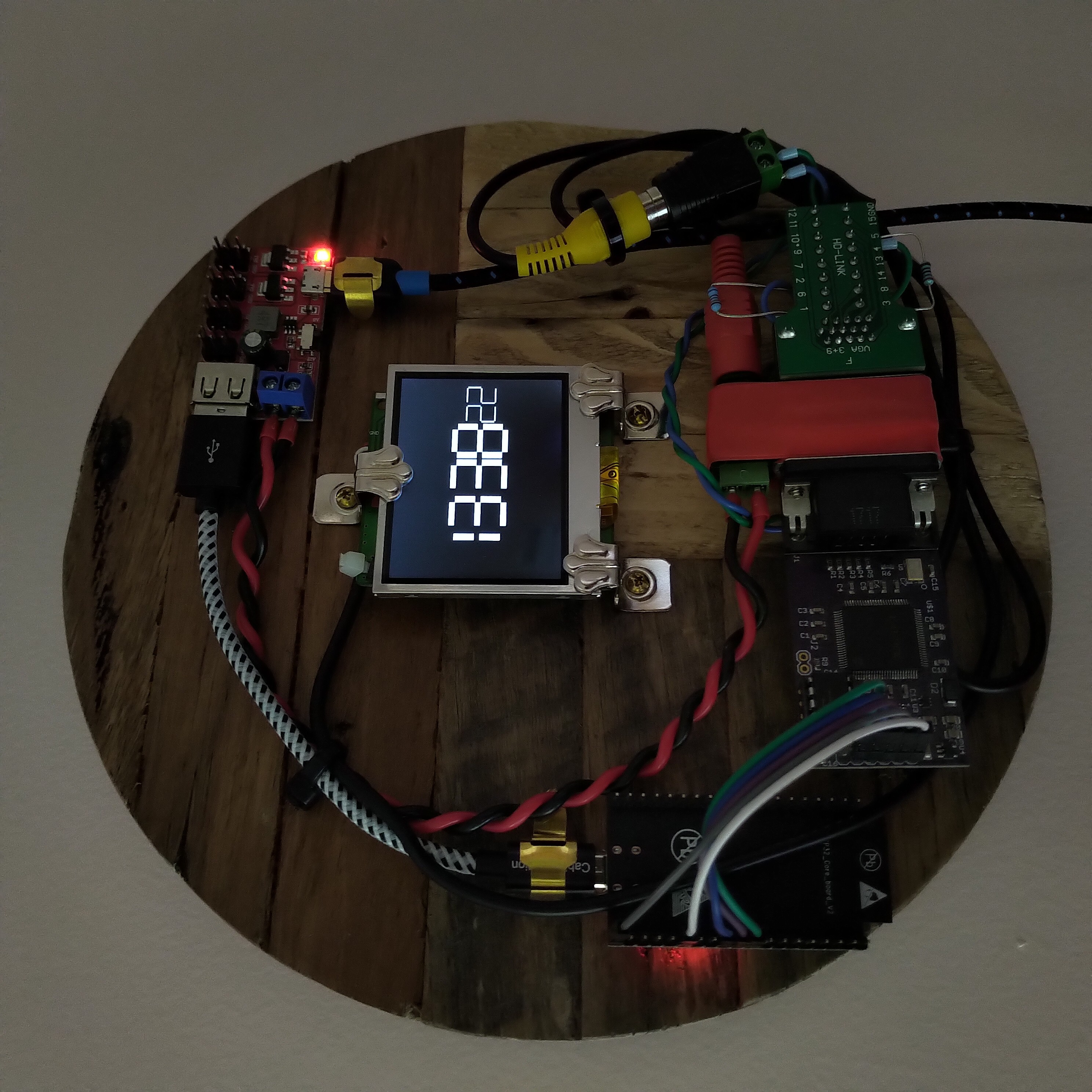
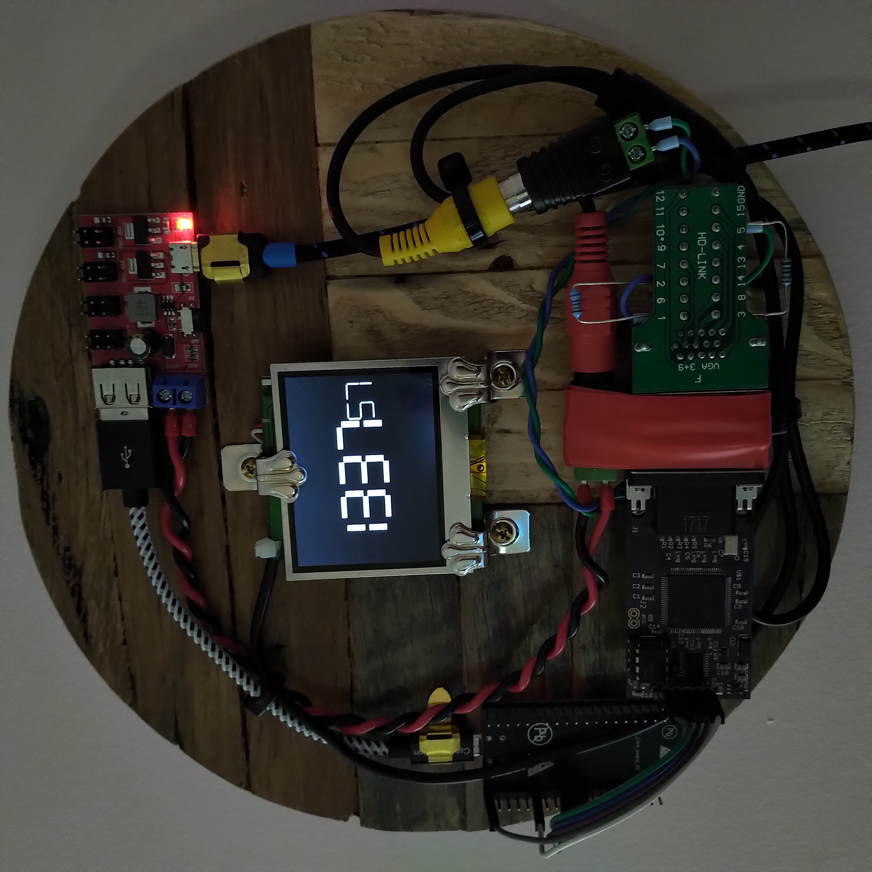
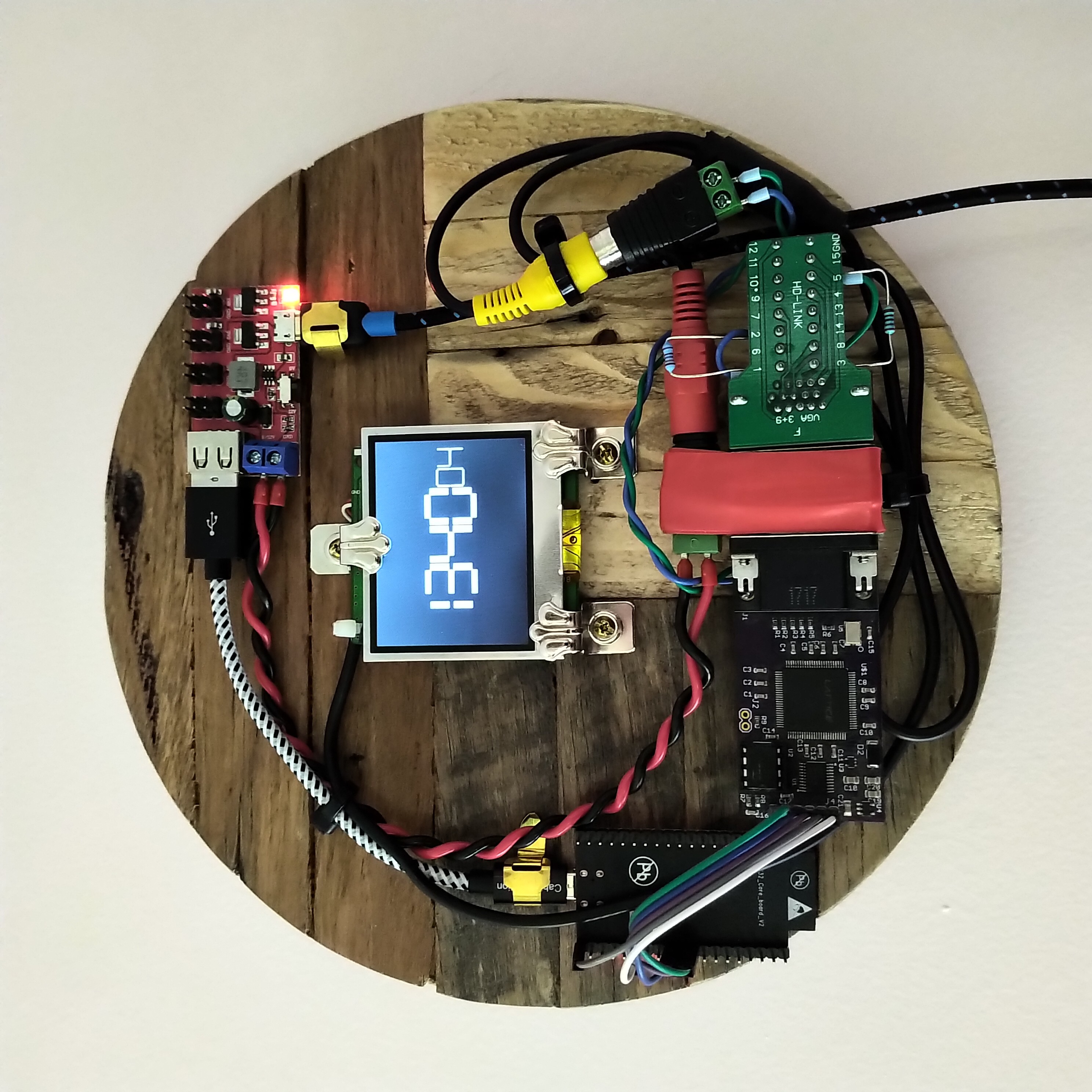
Using an ESP32 (DevKitC V2) to open a Telnet connection over the local network to an old Raspberry Pi One (Model B Rev 2), and repeatedly sending the Linux 'date' command to get the current time - then shifting out the digits returned to one of my old VGA1306 FPGA boards, which then uses a few external resistors on a VGA breakout board as an R2R DAC to output 7-segment digits as black-and-white NTSC composite video (not VGA) to the guts of an old 2.5" RCA Video TFT LCD! 😅
The inherent laggyness of this scheme is visible in the seconds counter on the clock - not a neat and precise march from zero to fifty-nine seconds, but more of a lurching stumbling drunken progression from minute to minute - and I love it! Obviously there are more precise ways of keeping time, but that was not the goal. This is art. This clock has a personality. This object is pure hack.
![]()
![]()
For the code on the ESP32 I used Arduino's default WiFiClientBasic.ino sketch as a skeleton to get a network connection, and also took inspiration from martydill's telnet code, to step through the following sequence:
1. connect ESP32 to wifi
2. connect ESP32 to raspberrypi host
3. respond appropriately to telnet protocol negotiations from the pi
4. wait for colon characters and automate sending the username and password, to login to the pi
5. wait for dollar sign character at the end of each command prompt and send "date +%t%H%M%S"
6. wait for the tab character returned with the output of the Linux 'date' command
7. read in the 6 digits of the time, HHMMSS (need to subtract 48 from the ASCII character values)
8. step through sending each pair of digits to the FPGA, packed as two 4-bit nibbles in a single byte
(total of 3 bytes = 24 bits shifted out, max digit value is 9 (1001 in binary) so only need 4 bits to represent)
9. return to step 5
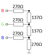
The VGA1306 FPGA logic uses each 4-bit value in the 24-bit register to assemble the seven segments of each digit on the screen. I originally designed the board to output 8-colour VGA, not composite video - so my hacky method of using it to generate black-and-white NTSC composite video was to use the three separate RGB signals combined to represent a single 3-bit digital-to-analog voltage value instead. There are already 270Ω resistors built-in on the Red / Green / Blue VGA output pins, so these are being repurposed as half of the 3-bit R2R DAC to get the necessary voltage levels for composite video (the remaining three external resistors in the DAC are on the VGA breakout board).
![]()
This got me close enough to the 0V / 0.3V / 1V values needed. Everything on the drunk wall clock is powered from a neat little 1.8V / 3.3V / 5V / 9V / 12V Power Breakout Board.
All of the code is on GitHub here (plus the Excel spreadsheet I used to layout the pixels for each digit).
I bought the lovely 'reclaimed-wood' base from this Etsy artist. The VGA1306 board was being produced by kitsch-bent a few years back, but CraftsbyDad has also been making some lately and selling them at-cost on Tindie.
But wait, there's more - the Raspberry Pi running the 'date' commands is also itself acting as a wall clock, using an Adafruit PiTFT shield and running tty-clock!
Last, but far from least, many thanks to these three guys down here for writing the NTSC Verilog code back in 2007! 😊
![]()
-
Frame-skipping at 109FPS to turn 8 colours into 15 'dazzling' colours the hard way, on the world's second worst video card?
08/07/2019 at 10:30 • 0 commentsWhen I first dipped my toe into the world of FPGAs and designed the VGA1306 (also known as 'easy_VGA') board, it was with the set goal of emulating the ubiquitous 128x64 pixel SSD1306 monochrome OLED screen – using a Lattice iCE40 FPGA to read in the SPI signals meant for the little screen, and then output up-scaled black and white VGA signals to a big screen instead. And so with this goal in mind, using a 25MHz oscillator for 640x480 pixels @ 60FPS and only a single resistor on each of the red / green / blue lines was more than enough – the fact that the RGB signals could then also be set in different combinations to achieve all eight glorious colours of the 3-bit RGB rainbow was a pure bonus!
But as I learned more over time and developed a taste for FPGAs, I have been able to squeeze more and more potential out of this minimal PCB – using it as a VGA output for the Nintendo GameBoy, as an old-school Snake or Breakout game, and even as an 80x60 character 'text-mode' video card for Arduino BASIC or a VT100 terminal emulator.
Inspired by Ben Eater's recent “world's worst video card” project where he used a 10MHz oscillator to output four-pixels-at-a-time within a standard 40MHz pixel clock timing, I started thinking about ways to work within the limitations of my fixed 25MHz oscillator (with no PLL available on the FPGA), and the hard-wired 3-bit RGB palette, and how I might be able the push it a little further... it occurred to me that I could possibly double my 8 colours, up to 16 colours, if I set it up so that some pixels only appeared every second frame – so they would then appear as a darker shade of that colour? At first this just resulted in a lot of flickering, and I quickly realised that the frame rate would need to be much higher in order for a pixel that was only appearing every other frame to be perceived as a steady pixel of a darker shade, rather than as a quickly flickering pixel of the same shade!
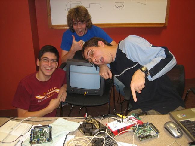
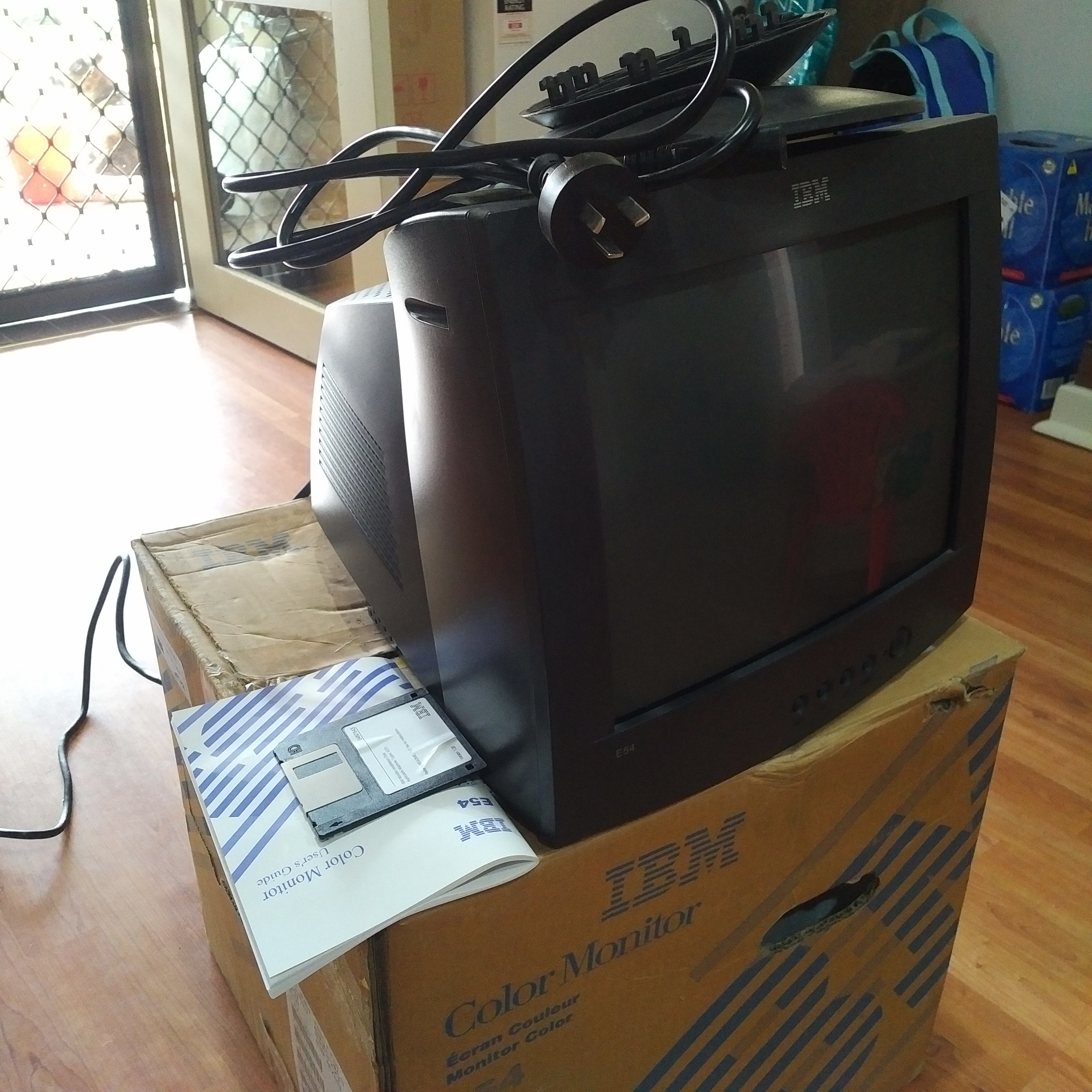
I found details for standard VGA timings running at up to 100FPS, and figured out that if I could divide my 25MHz clock by one-and-a-half, then I would be close to the right frequency for pushing out those four-pixels-at-a-time. I managed to find some handy divide-by-1.5 verilog code in an old comp.lang.verilog newsgroup post from 2005, but at this point another problem popped up – none of the MANY flat-screen monitors in the house were actually capable of running at 100Hz! But, I remembered an old IBM CRT monitor that had been sitting in a corner gathering dust at work, and I brought it home with me the next day – still in the box, including user manual and 3½ inch floppy disk.
![]()
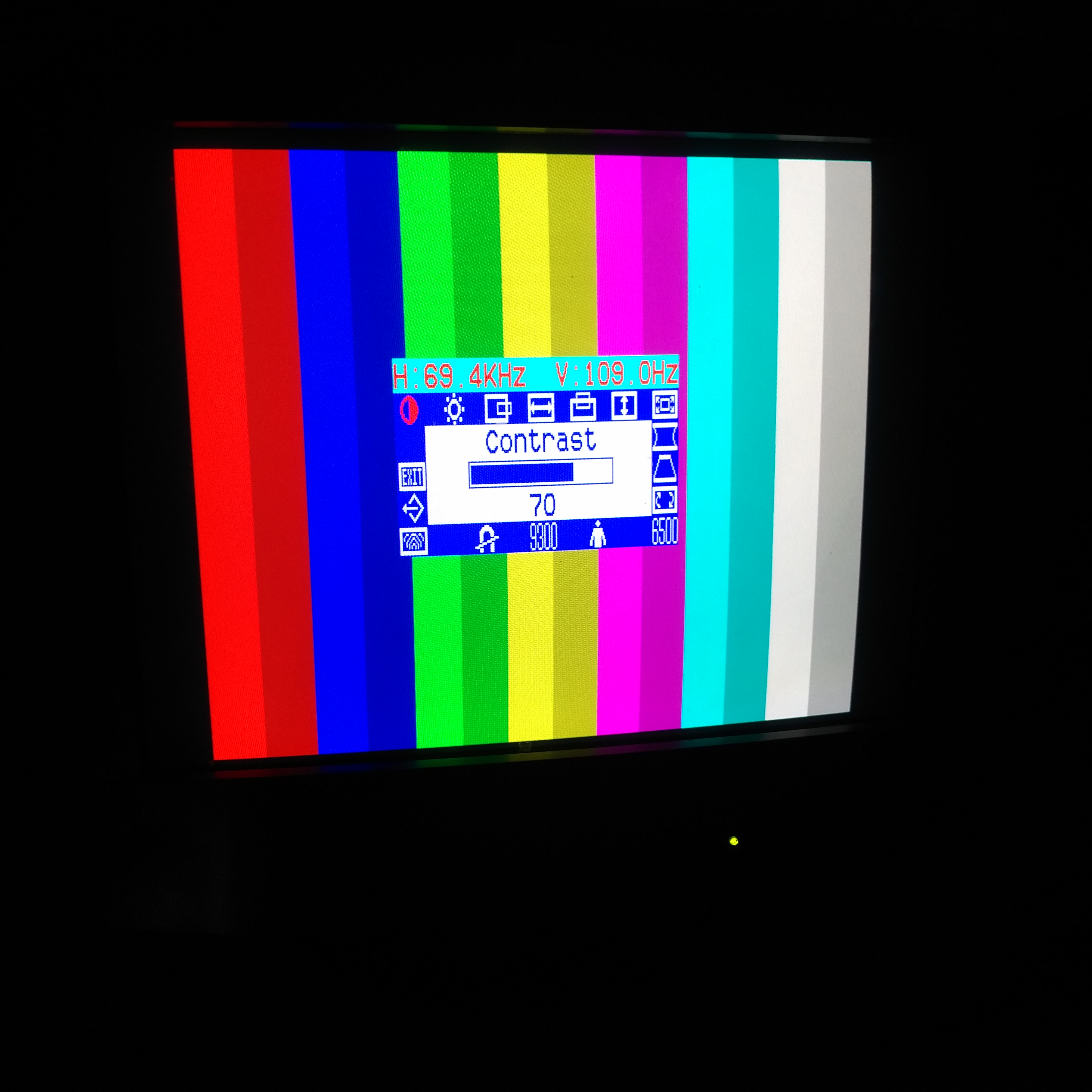
Happily, this monitor has a scanning frequency of up to 120Hz vertical and 69kHz horizontal – now that's more like it! After some experimenting I was able to push it up to 109Hz / 69.4kHz, and the flickering went away, and my 15 colours were on screen 😃 (not 16 colours – no darker shade of black, sadly).
![]()
Recording video of CRT monitors is difficult at the best of times, but the frequency I am running it at here makes it even more troublesome – I was eventually able to get some good recordings though using an iPhone app that allows for manual adjustment of the shutter speed (also, by setting the shutter speed to 1/110 you can actually see the bars for the darker colours switching off and on).
Wondering what a good application of this new capability may be, I found David Hansel's Altair 8800 simulator for the Arduino Due – specifically the extension for simulating the original Cromemco Dazzler graphics card! The Dazzler gave an Altair 8800 the ability to output RGBI (15 colour) video at 64x64 pixels and was 'cutting-edge' at the time. After some time studying David's...
Read more »
 RomanS
 Wenting Zhang
 Fabien-Chouteau
 Hendra Kusumah
 deʃhipu
 sjm4306
 Stef64kb