-
Light Bulbs Seesaw
04/08/2021 at 10:01 • 0 commentsThis article is about a light bulbs seesaw.
![]()
You can see how my structure works in this video:
Do not worry. This circuit is not ask complicated as it looks in the photo.
I made the seesaw from the following materials:
- three old brushes for the seesaw,
- three 1.5 V light bulbs (you might need more in case you burn the bulbs),
- three light bulb screws/holders,
- AA battery metal case plates (I straightened them out with pliers many years ago) - I used two to hold the seesaw (yellow in colour) and two for the contacts,
- metal rod (to hold the seesaw),
- AA battery (I could have used AAA, C or D battery),
- AA battery harness (I could have used AAA, C or D harness),
- insulated metal wires,
- 1 mm thickness metal wire.
Step 1: Make the Seesaw
I made the seesaw very quickly by attached three old paint brushes with 1 mm thickness metal wire.
For the second step is attached all of the three light bulbs. Then I connected positive (red) and negative (black) wires to the centre light bulb as shown in the photo (I used yellow wire as an extension of red and black wires that were too short).
![]()
Connecting the battery after this step would turn ON the centre light bulb.
Then I extended the red and black wire even further. I connect red wire to the bulb on you right and black wire to the bulb on your left. Both of the two remaining bulbs were still OFF. I connected negative wire (black) to metal plate on your right and positive wire (red) to the metal place on your left. You can see that at the bottom of each light bulb there are many turns of 1 mm metal wire. Those turns are used as contacts from light bulbs to the metal plates, thus allowing the current to flow into the bulb on the edge of the seesaw when the seesaw gently hits one of the plates.
Step 2: Testing
When testing and making the seesaw you can easily short the positive and negative pins. This might cause the battery to explode.
Thus you need to be careful.
Conclusion
This design could be modified into a funny toy.
-
Computer Fan Aircon
01/20/2021 at 08:22 • 0 commentsThis article is about the air conditioner that can be made from a computer fan.
The fan blows the air out of the plastic box filled with ice to cool the ambient temperature.
Aircon 1:
![]()
Aircon 2:
![]()
I thought of this idea when my brother found a few old computer fans on the street soaking in the rain.
Step 1: Design the Fan
This idea is not new and there are a number of videos on YouTube.
My design does not include the lid. You might need this if you are putting your fan in your car because the car could me moving on a rocky or bumpy road turning inside contents upside down. You can try using food containers with the lid to avoid this problem.
Step 2: Make the Fan
The first thought that comes to mind is which way I attach the fan to the plastic container. One side is sucking air in and the other side is blowing the air out.
We all know that if we put a hand near the computer fan at the back of a typical desktop PC we will feel a blow of air, flowing out of the computer. This is why there is no need to connect the fan to the 12 V battery before attaching this component to the plastic package. We know what the back of the computer fans looks like:
Aircon 1:
![]()
Aircon 2:
![]()
Step 3: Testing
I connected the two aircons that I made to 12 V battery:
Aircon 2:
Step 4: Testing With the Ice
Aircon 1:
Aircon 2:
Step 5: Testing Tricks
Aircon 1:
Aircon 2:
-
Button ON OFF Switch
03/24/2020 at 07:49 • 0 commentsThis article shows you how to make an ON OFF switch with a button.
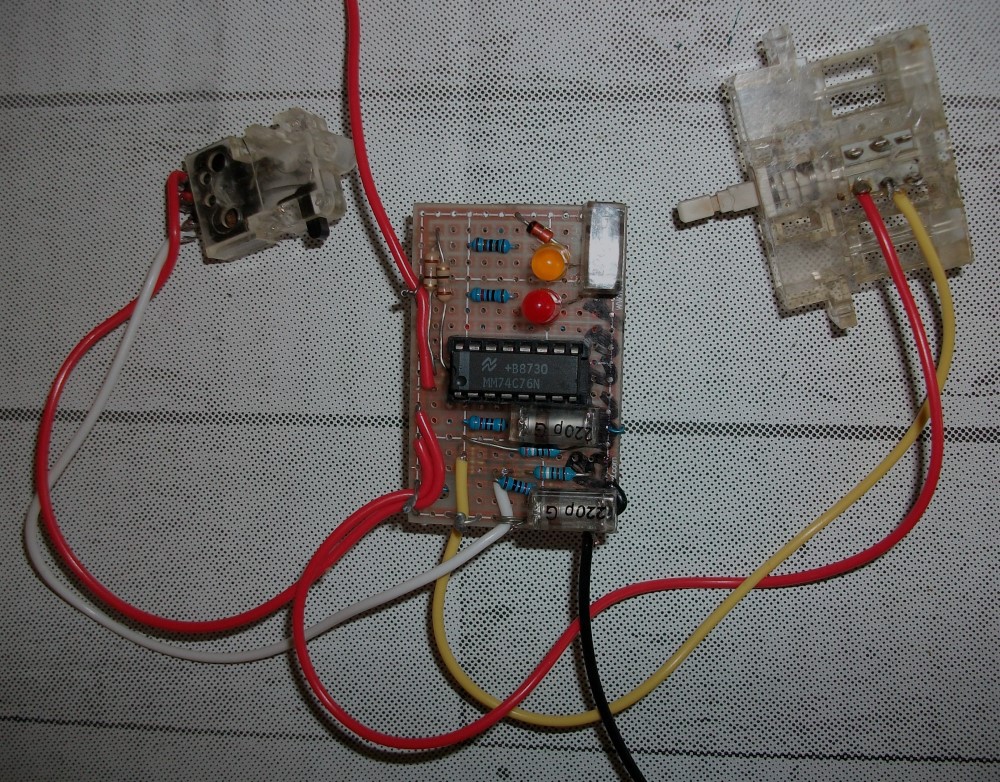
![]()
You can see from the photo above that I implemented this circuit with an old TTL (Transistor Transistor Logic) JK flip-flop IC (7476). However, you can use D flip-flop and CMOS is always better than TTL that has been obsolete for many decades now.
The micro chip is inserted into a wire wrap socket. I hardly used a soldering iron and you might be able to avoid it if you want to build this circuit. You might need to user a bigger matrix board.
The IC (Integrated Circuit) has two JK flip-flops inside. You can search for specifications online and find that all inputs need to connected to logic "1" (5 V power supply) and each of the clock inputs to two two buttons.
You can see my circuit working in the video:
Step 1: Design and Build Input Circuit
The video does not show that at times the LED is not turning ON or not turning OFF even after the button is pressed. This is because I do not have a USB oscilloscope and cannot see the input entering the JK flip-flop clock input when the button is pressed.
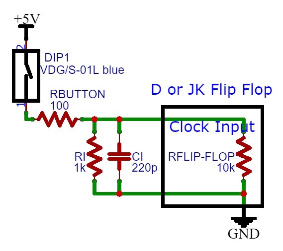
You can see the clock input circuit that I used:
![]()
Removing the RC filter that consists of two resistors and one capacitor will allow a spiky signals to enter the flip-flop clock input. Some people who are not experts in digital or electronic design might think that when a button is pressed ON and OFF a perfect step function signal (rectangular/square shaped waveform) is entering the flip-flop (switching from 0 V to power supply voltage ) or any other input device. This is never the case unless you have a very expensive and perfect button. There are small spikes in the waveform due to mechanical imperfection of the button metallic contacts. This is why I designed an RC low pass filter.
The frequency of the RC filter equals to:
fLP = 1/(2*pi*Ci*R)
Where: R = 1/(1/Ri + 1/Rbutton + 1/Rflip-flop)
Calculating this value could be a very complicated problem because you might not be able to easily calculate the flip-flop resistance. However, you can measure it as flip-flop clock inpu voltage divided by input current. Also, you can assume that both Ri and Rflip-flop are a lot higher than Rbutton 100 ohm resistance thus can be ignored.
Higher capacitor value will filter more button spikes. However, they might also filter the input signal, increasing the step function rise time and the flip-flop would not turn on. I chosen 220 pF capacitor via trial and error. This capacitor resulted in best circuit performance.
When Ci capacitor voltage is zero the current coming from 5 V power source is Vs / Rbutton = 5 V / 100 ohms = 50 mA. Thus reducing Rbutton to zero (short circuit) will cause Ci capacitor failure. I suggest that you use a 100 ohms resistor because the flip-flop might need a high input current. Assuming that after the capacitor is fully charged the current entering Ri and Rflip-flop is 2 mA, the voltage drop across the Rbutton will be as high as 2 V if Rbutton is 1000 ohms. Than means the voltage entering is flip-flop is only 3 V. The flip-flop might need at least 3.5 V to accept the input as a logic "1". This is why Rbutton resistor needs to be small in resistance value.
Next step is choosing Ri resistor. When the button is disconnect the flip-flop is supplying small current to the Ri resistor. Thus there is issue with flip-flop maximum input current to accept the input voltage as a "0" when the button is OFF. Assuming the maximum flip-flop input current no more than 300 uA = 0.3 mA. That means the maximum input voltage when the button is disconnected will equal to 0.3 V. If this flip-flop accepts a logic "0" for voltages below 0.7 V (greater than 0.3 V) means that the circuit will work.
Step 2: Power Supply
The power supply can be implemented with a 5 V voltage regulator. It could be a better option than using a zener diode, yet might cost more money if you have to order this IC. You can implement a 5 V zener diode...
Read more »


 Dominik Meffert
 Christopher Tan
 bobricius
 Maarten Janssen
 agm777
 PROFESOR
 Dmitry
 Beto Green
 Natalia
 Psyrax
 Andrey Kupreychik
 Roman Weitendorf
 Jeremy
 NaranInc
 Andrea De Napoli
 s7a73farm
 Jason Cho