-
Touch Garden Light
07/28/2020 at 10:41 • 0 commentsThis article shows you how to make a touch garden light shown in the photo below:
![]()
I used a encasement from an old solar garden light.
The light turns on when the two contacts from the circuit are connected by human hands or human fingers.
You can see my circuit working in this video:
I thought of this idea after reading the following article that contains similar circuit to mine:
https://www.instructables.com/id/Cheap-Touch-Lamp
Step 1: Design the Circuit
I drawn the circuit in PSpice simulation software:
![]()
My circuit uses a Darlington pair unlike the circuit in the link above that uses voltage follower current amplification. I tried using a single Darlington pair power transistor and I found that the gain was insufficient for the LEDs to turn ON.
Calculate the maximum LED current:
IledMax = (Vs - Vled - VceSat1 - Vbe2) / Rd / 2
Rd = 33 ohms + 47 ohms = 80 ohms:
= (4.5 V - 2 V - 0.2 V - 0.7 V) / 80 ohms / 2
= 0.01 A = 10 mA
Rd = 82 ohms:
= (4.5 V - 2 V - 0.2 V - 0.7 V) / 82 ohms / 2
= 0.00975609756 A = 9.75609756 mA
Calculate the time constant, the approximate time it takes for LEDs to turn OFF after the contacts are disconnected:
Tc = Rbe * Cbe = (1*10^6 ohms) * (470*10^-9 F) = 0.47 seconds
After 5 times constants (5*Tc = 2.35 seconds) the Cbe capacitor is considered to be completely discharged.
Step 2: Simulations
Simulations show the predicted maximum bright LED current of about 14 mA.
![]()
Step 3: Make the Circuit
I placed this circuit at the bottom part of the device:
![]()
You can see the four NPN BJT transistors (connected in Darlington pair), the 33 ohm Rd1 resistor and the 470 nF Cbe capacitor.
I placed this circuit inside the glass ball:
![]()
You can see the 10 kohm Rb resistor, 47 ohm Rd2 resistor (Rd = Rd1 + Rd2 = 33 ohm + 47 ohm = 80 ohms) and the two bright LEDs.
Step 4: Encasement
I placed the first circuit inside the metal part of the garden light.
![]()
Step 5: Put the Lid On
I attached the lid with masking tape:
![]()
You can see how well the lid covers the circuit:
![]()
Step 6: Testing
At first I made the circuit without the Rbe resistor to see what happens.
![]()
You can see that without the Rbe resistor the lamp takes a long time to turn OFF.
-
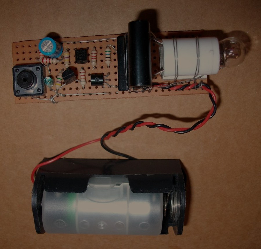
Turn ON in the Dark Light Bulb
05/19/2020 at 03:29 • 0 commentsI made this circuit many years ago.
![]()
The small green component in the circuit is the photo diode. This photo diode can be modelled as a current source that supplies current when lights are ON.
The light bulb turns ON in the dark for a few seconds. This give you enough time to find a torch that can be used for emergency lighting or go to bed if you are going to sleep. There is also a button shown in the circuit that turns OFF the light bulb earlier to save battery power.
Step 1: Design the Circuit
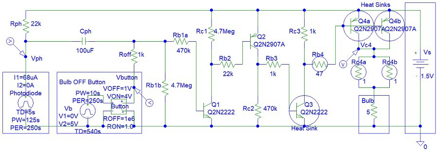
I drawn the circuit in old PSpice software to save time.
![]()
This circuit can be implemented with MOSFET transistors. Rc4a and Rc4b resistors are not essential. You can see I did not use them in my circuit. They are needed for short circuit protection.
I used a 10 uF Cph capacitor for the circuit that you see in the video. However, I specified 100 uF capacitor in the simulations because I considered the option of keep the light bulb ON longer should you choose to make this circuit.
The collector resistors (Rc1, Rc2 and Rc3) and Rb1b are needed to ensure that the transistors OFF when the lights are ON. The collector-emitter pins of each transistor can be modelled as open circuit when Vbe (base-emitter) voltage or input base current are zero. Thus without the collector resistors (Rc1, Rc2 and Rc3), the input of connected/cascaded transistor will be disconnected. However, you can see that my circuit is still working without those resistors.
When lights are OFF, Vph voltage is almost equal to supply voltage, Vs and discharging the Cph capacitor will turn OFF the light bulb.
Calculate the Cph capacitor charge time when lights are OFF with the button:
(the Cph capacitor can be considered fully discharged after 5 time constants)
Tcph2 = 5*Cph*(Roff + Rph) = 11.5 seconds
Calculate the Cph capacitor charge time when lights are OFF without the button:
Tcph2 = 5*Cph*((Rb1a*Rb1b)/(Rb1a + Rb1b) + Rph)
= 5*44.9272727273 seconds = 224.636363636 seconds
(later the simulations will show that the light bulb turns OFF only a few seconds after the first time constant (not five time constants) because the transistors need minimum current input to keep the light bulb ON)
When lights are ON, Vph voltage is zero and discharging the Cph capacitor will turn OFF the light bulb. However, the Cph capacitor could be already zero if the lights were OFF for a long time.
Calculate the Cph capacitor discharge time when lights are ON with the button:
Tcph2 = 5*Cph*Roff = 0.5 seconds
Calculate the Cph capacitor charge time when lights are OFF without the button:
Tcph2 = 5*Cph*((Rb1a*Rb1b)/(Rb1a + Rb1b))
= 5 * (100*10^-6) * 427,272.727273 ohms
= 5*42.7272727273 seconds = 213.636363636 seconds
Calculate the equivalent Rc4 resistance:
Rc4eq = (Rc4a * Rc4b) / (Rc4a + Rc4b) = (1 ohms) * (1 ohms) / (1 ohms + 1 ohms)
= 1 / 2 = 0.5 ohms
Rc4a and Rc4b can be replaced with one 0.5 ohm resistor. I used two resistors to reduce the power dissipation for each resistor.
Calculate the potential voltage across the Rc4 and Rc4b resistors:
Vrc4 = Rc4eq * Ibulb
= 0.5 ohms * 0.3 A = 0.15 V
This means that the 1.5 V light bulb is receiving a voltage of:
Vbulb = Vs - Vcr4 = 1.5 V - 0.15 V = 1.35 V
Calculate the power dissipation for Rc4a and Rc4b resistors:
Prc4eq = Vrc4 * Ibulb = 0.15 V * 0.3 A
= 0.045 W = 45 mW
Thus each resistor (Rc4a and Rc4b) will dissipate: 45 mW / 2 = 22.5 mW
Calculate the minimum transistor Q4 current gain to ensure saturation:
BetaMin = ((Vs - VQ4sat) / (Rbulb + Rc4a/2)) / ((Vs - Vbe - VQ3sat) / Rb4)
= ((1.5 V - 0.2 V) / (5 ohms + 0.5 ohms)) / ((1.5 V - 0.7 V - 0.2 V) / 47 ohms)
= (1.3 V / 5.5 ohms) / (0.6 V / 47 ohms) = 18.5151515152
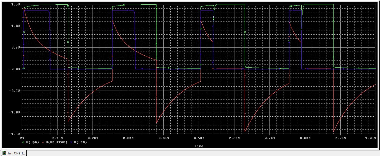
Step 2: Simulations
Simulations shows two cycled without the OFF button and two cycles with the OFF button:
![]()
-
Parcel Automation System
05/17/2020 at 10:13 • 0 comments1. Introduction
At the end of my RMIT University engineering degree there were a number of 3-semester projects advertised to third year students. One of those projects was a post office automation system. I selected this project as my first preference. However, a few weeks later I received an email stating that I was selected for project number 1. It was Ericsson Australia optic fibre research three semester project that could lead to a career at Ericsson Australia. Thus I was forced to abandon my dream of creating the post office automation system that was not a paid project and someone else ended up working on this project.
I completed my Ericsson Australia project with three other students that were also selected to work with me in November 2002. The following year our Ericsson project received an RS Component Award.
However, over the last two decades, occasionally I would think about the different electronic or mechanical solutions that I could have used to implement the post office automation system.
This system can be used not only for parcels but for letters as well.
2. Measuring the Box Size - Electronic
In the project description it was mentioned that the box size need to be measured with a light/infrared sensor array. The volume of the box covering the light will give an indication of how many sensors are receiving ambient/infra red light and thus determine the dimension of the box. The array can me implemented with light depended resistors (LDR)/photo diodes. Three arrays will me needed, an array for each of the three dimensions of the box. Each array must consist sensors placed in a straight line.
I considered the possibility of sensors being influenced by shadows. Thus I was considering the use of infrared sensors with infra-red emitters. Thus I began to think that using ultrasound to measure the distance to the box is a better option to determine the box dimensions. However, detecting small reflected ultrasound waves could be a more complicated challenge if this distance from sensor to box is very long. Then I realised that the parcel can me placed in light shielded box that will prevent any ambient light interference.
The best solution would be to use an array of laser tags, placed on the other side of the box that will shine on to the photo sensors. This method will give a clear indication if the box is covering the sensor or not.
3. Measuring the Box Size - Mechanical
A more reliable idea could be using an array of mechanical buttons. If you put the box on the edge of the post office automation encasement and apply as gentle force then you will be activating the buttons with the box volume. A reliable mechanical sensors might be needed that ensure a change in logic output because a possible low pressure from box might fail to turn a given button ON. If an parcel sachet/envelope is used instead of the box then long levers or shafts will be need to activate the buttons because we know that sachet/envelope parcels do not have flat sides like boxes.
4. Measuring the Box Weight
The box weight can be measured with pressure sensors. A pressure sensor can be created with a spring and photo sensor/ultrasonic sensor by measuring the length of the spring during spring deformation/compression. After I graduated I would study MEMS (micro-electromechanical systems) pressure sensors that are be used in digital scale devices.
5. Sensor Array Implementation
The photo sensors can be biased with a 1 kohm resistor. A box covering the photo diode array will ensure that no light can enter the photo diode/photo transistor. The laser tag is so powerful and directional that only one photo diode/LDR will sense the ambient light form the laser tag on the other side of the box. Each photo sensor corresponds to 1 cm or 1 inch dimension.
The photo sensor can be biased to provide a logic "1" or logic "0" output when light from the laser tag is generating sensor current. To switch from logic...
Read more »


 Lutetium
 Kevin Harrington
 Jan B.
 Owen Trueblood
 Pure Engineering
 Memo Santos
 Brendan
 Max-Felix Müller