 Dylan Brophy
I hadn't looked at this project in a long time, and the other day I was browsing it and noticed several comments asking for the schematics. But hadn't I uploaded schematics? So I double checked the files, found the attached schematic zip, and decided to open it up. Oh geez, what a mess! It had been created with a very old KiCad version compared to today, and I don't think I uploaded the symbol libraries, so the schematics were useless. I can see now why people asked for the schematics!


Upgrading the board
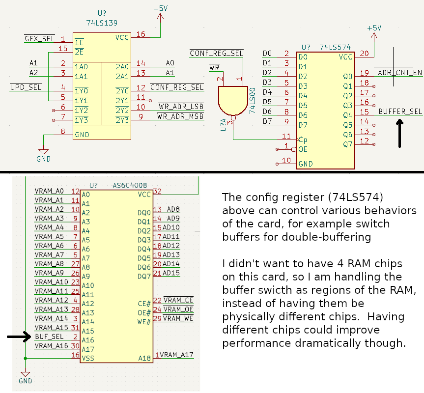
If you saw my log in #Arduino Desktop, then you'll know that I mentioned this project, in that I may want to add it to another Teensy or ESP32 based computer system. A Teensy 4.1 could write a lot of data to VRAM very quickly, which would be great for drawing bitmaps, and in-between the uPD7220 can draw other shapes. In that log I also mentioned double-buffering the uPD7220, so there would effectively be two RAM banks, which could be switched by some command. To my knowledge, the uPD7220 does not support this, so I needed to add the logic myself. I'm still working on the schematic, but here's where we are so far:
 I'm not a huge fan of the old board's low resolution. I want at least 640x480, if not higher. Adding more memory for this is quite easy, and in the new schematic this is already handled - the hard part is getting the clock speeds high enough. The uPD7220 can clock at 6Mhz, and the current card gets this by dividing it out of a 12Mhz clock. With a Z7220 the clock is a bit higher, 8Mhz and 16Mhz respectively, but this is nowhere near the pixel bandwidth needed for higher resolutions. My solution to this will be to divide the uPD7220's clock one or two times so we can get 24Mhz or 48Mhz pixel clocks on a uPD7220. That should allow us to get way better resolutions:
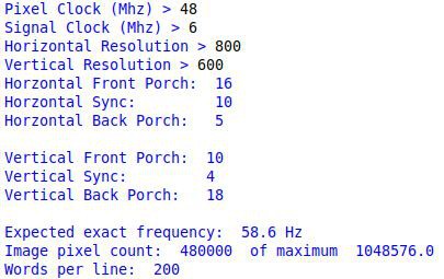
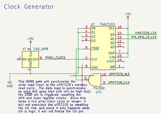
Here is the current clock generator circuit for the new board, which should behave exactly the same as the old board; its job is to generate clocks for the board and to control when pixels are loaded into the output buffer:
 Anyway, I have more stuff to figure out with the board. If any of you have good ideas on the clocks and loading twice the pixels from RAM, let me know :)
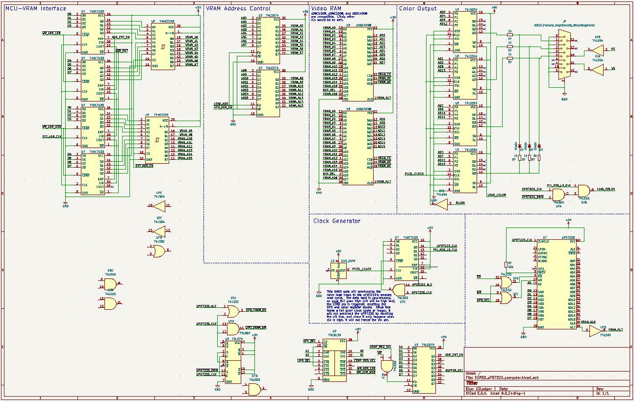 Hopefully my schematics are prettier and more useful this time; I think they will be.
Discussions
Become a Hackaday.io Member
Create an account to leave a comment. Already have an account? Log In.