Sebastian
Introduction
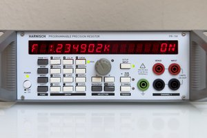
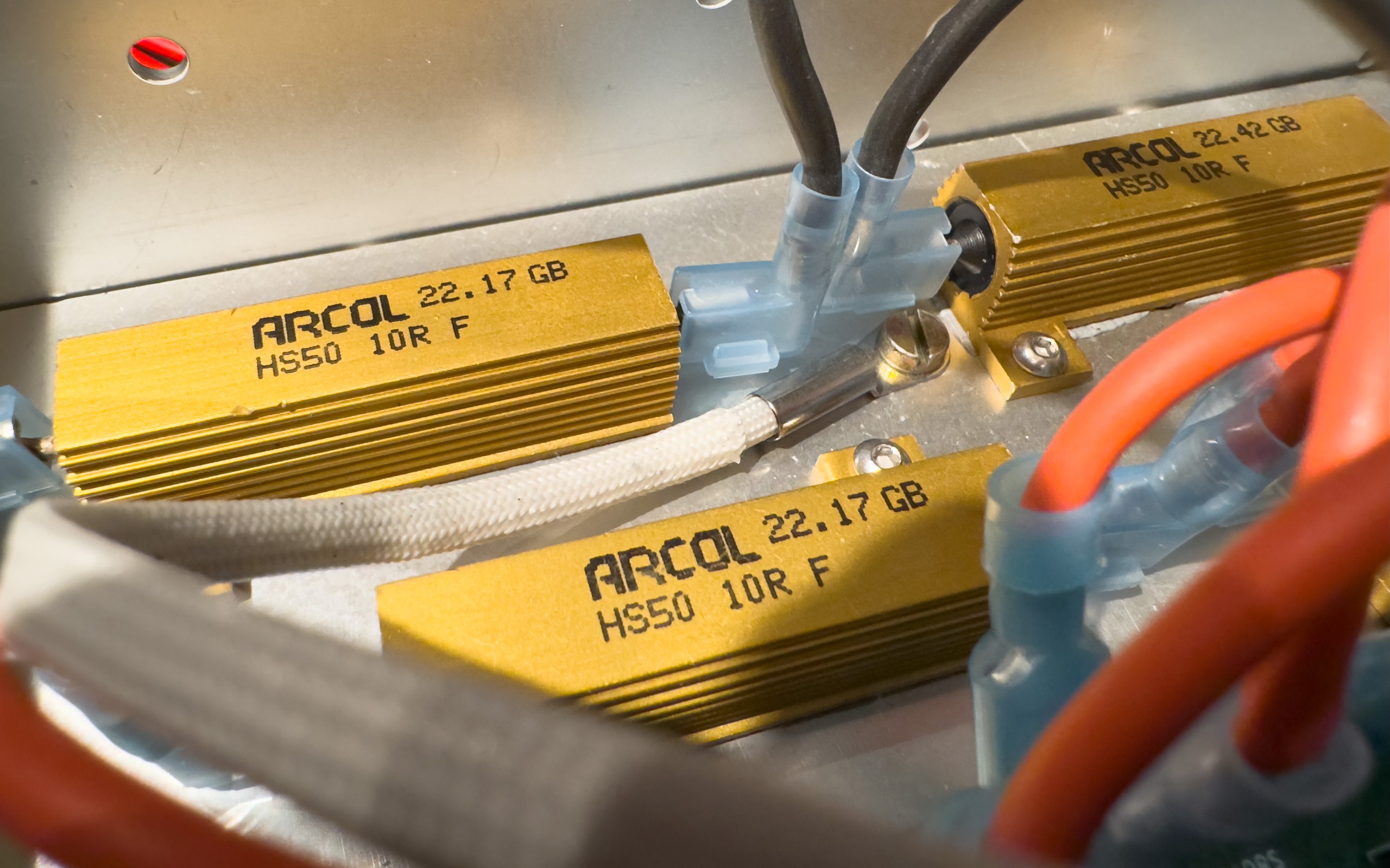
For the performance checks of my Agilent 6811B AC Power Source/Analyzer (375VA) I needed a 20 Ohm resistor with a ton of power handling capability. The original plan was to mount 8 wire wound 50W resistors on a heat sink and be done with it. Then I thought: Why not reuse all the code I've already written for the programmable resistor and build a programmable high power resistor that can complement my DC load for AC applications...
Features and preliminary specs
| Parameter | Value / Description |
|---|---|
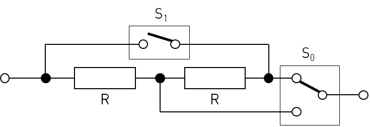
| Resistance range (nominal, Ohm) | short circuit, 1.25 to 80 Ohm, open circuit: 0, 1.25, 1.429, 1.538, 1.667, 1.818, 2, 2.143, 2.222, 2.273, 2.308, 2.353, 2.5, 2.727, 2.857, 2.941, 3, 3.077, 3.158, 3.333, 3.448, 3.529, 3.636, 3.750, 4, 4.167, 4.286, 4.444, 4.615, 5, 5.263, 5.455, 5.714, 5.833, 6, 6.5, 6.667, 7.143, 7.333, 7.5, 8, 8.333, 8.571, 9, 9.167, 9.375, 10, 10.667, 10.909, 11.111, 11.667, 12, 12.5, 13.333, 13.636, 14, 15, 15.385, 16.667, 17.143, 17.5, 18.333, 19, 20, 21.667, 22.5, 23.333, 24, 25, 26.667, 27.5, 28.333, 29, 30, 31.667, 32.5, 33.333, 34, 35, 36.667, 40, 42.5, 43.333, 44, 45, 46.667, 50, 55, 60, 65, 70, 80 |
| Setpoint resolution | settable to 1 mOhm, selects closest supported resistance value |
| Short-term setpoint accuracy estimate | <= 1% of nominal value + 0.2 Ohm |
| Display resolution | three decimal places (fixed) |
| Thermal drift (estimate based on design) | <=50ppm/K |
| Power/current rating | Depends on resistance setting. Limiting values are calculated and displayed. Up to ~150 W continuous (400W peak) or 6A, whichever is lower |
| Bandwidth | unspecified |
| Calibration modes | - Uncalibrated: Switches are activated according to entered setpoint, display shows setpoint - Two-wire (2W), Four-wire (4W): The resistance value closest to the entered setpoint is selected |
| Operating modes | Fixed: On trigger, no change Step: On trigger, step to trigger setpoint value Up: On trigger, increase setpoint (auto, linearly, 1-2-3-4-5-6-7-8-9, 1-2-5, 1-3) Down: On trigger, decrease setpoint (linearly, 1-2-3-4-5-6-7-8-9, 1-2-5, 1-3) List: See list mode |
| List mode | Up to 100 values with individual dwell times - Start: on trigger; or immediately after mode selection - Step: - Auto: Advance index automatically, solely based on dwell time - Trigger: Advance index on each trigger event, ignoring the dwell time - Once: Advance index on each trigger event, only after dwell time elapsed |
| Switching | - fast (default) - break-before-make |
| Protection | Over temperature protection (OTP) |
| Trigger | Source: Bus, Immediate, Manual, Timer Mode: Continuous, Single Parameter: - Delay, - Holdoff, - Time (0.01 s .. 10^7 s; Source: Timer) |
| Command and trigger execution | 10ms loops |
| User interface | - 16x2 Dot Matrix display: - Primary display: Resistance setpoint, (max.) heatsink temp. - Secondary display: - limiting values (voltage, current, power) - trigger state - uncalibrated resistance value |
| User presets | 0-9 (0 is restored on power-up) |
| Interface | - Input and Sense: 4mm safety banana jacks - USB (Virtual COM port) |
| Fans | Two temperature controlled 60mm fans (12V, 4500 rpm) |
| Power supply | Switch mode |
Typical applications
- (AC) Power supply tests
- Audio amplifier tests
Note
All information is provided "as is" without any warranty whatsoever. Although I have compiled the information to the best of my knowledge, there might be errors. You use the information at your own risk.

 NickB
NickB
 Yann Guidon / YGDES