 Marcin Saj
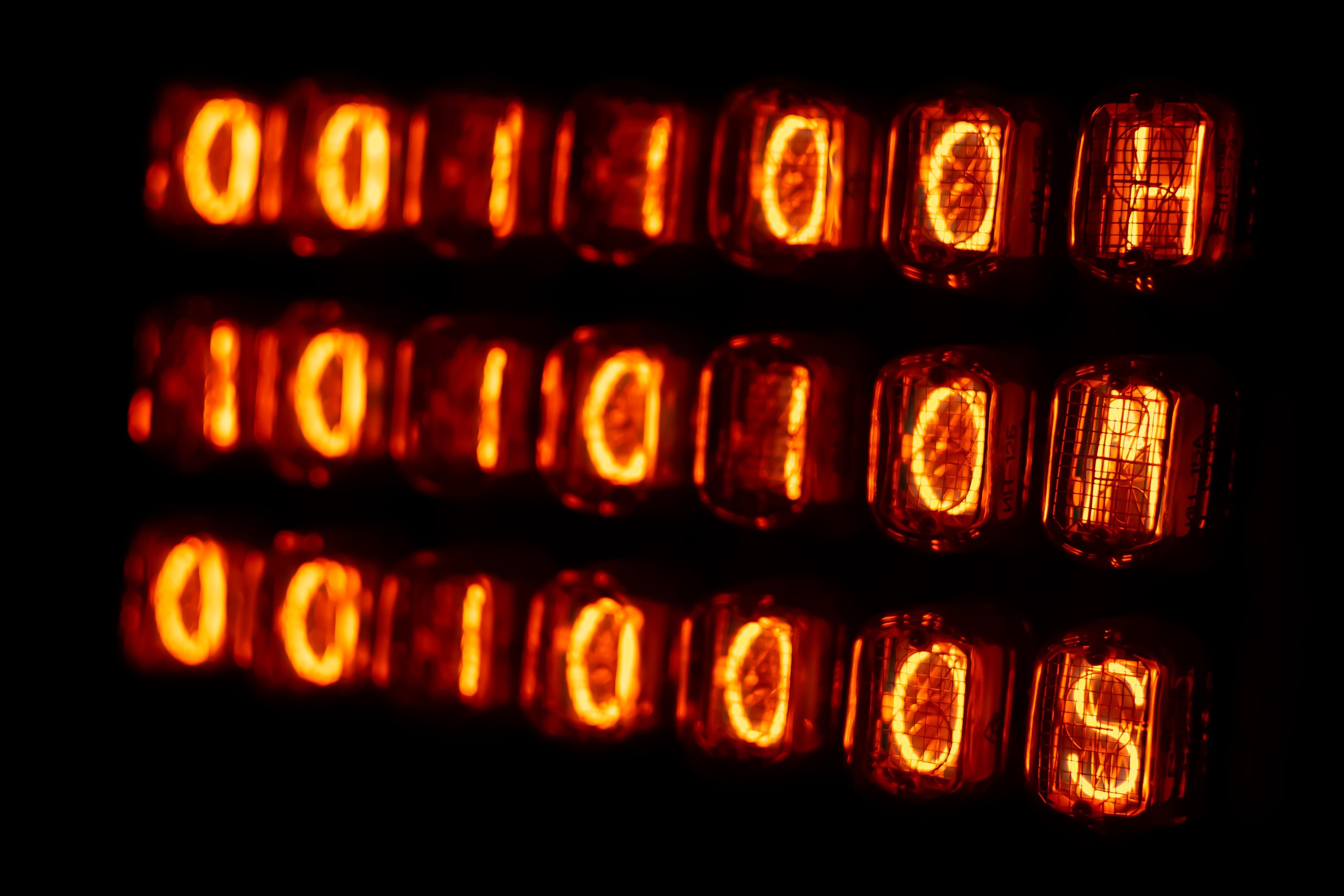
FEATURES & COMPONENTS.
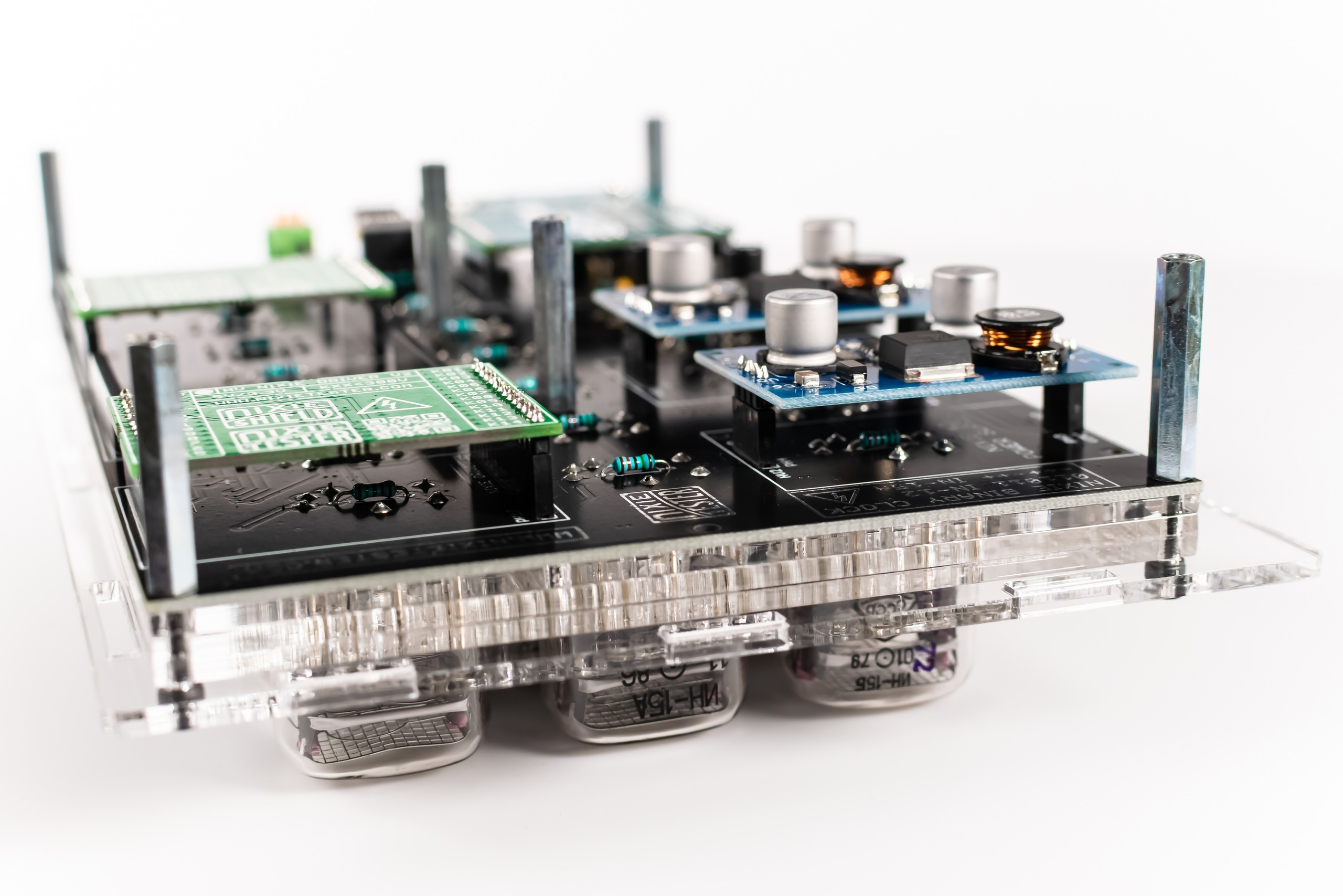
- Modular design
- Compatible with 5V/3.3V boards – Arduino Uno, Micro, Nano, Nano Every, Nano 33 IoT etc.
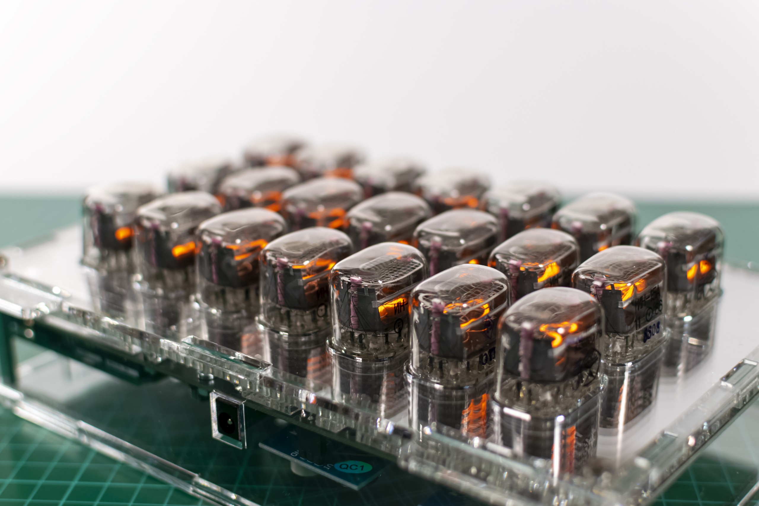
- Hours “H” and seconds “S” indicators IN-15B nixie tubes, minutes “M” IN-15A
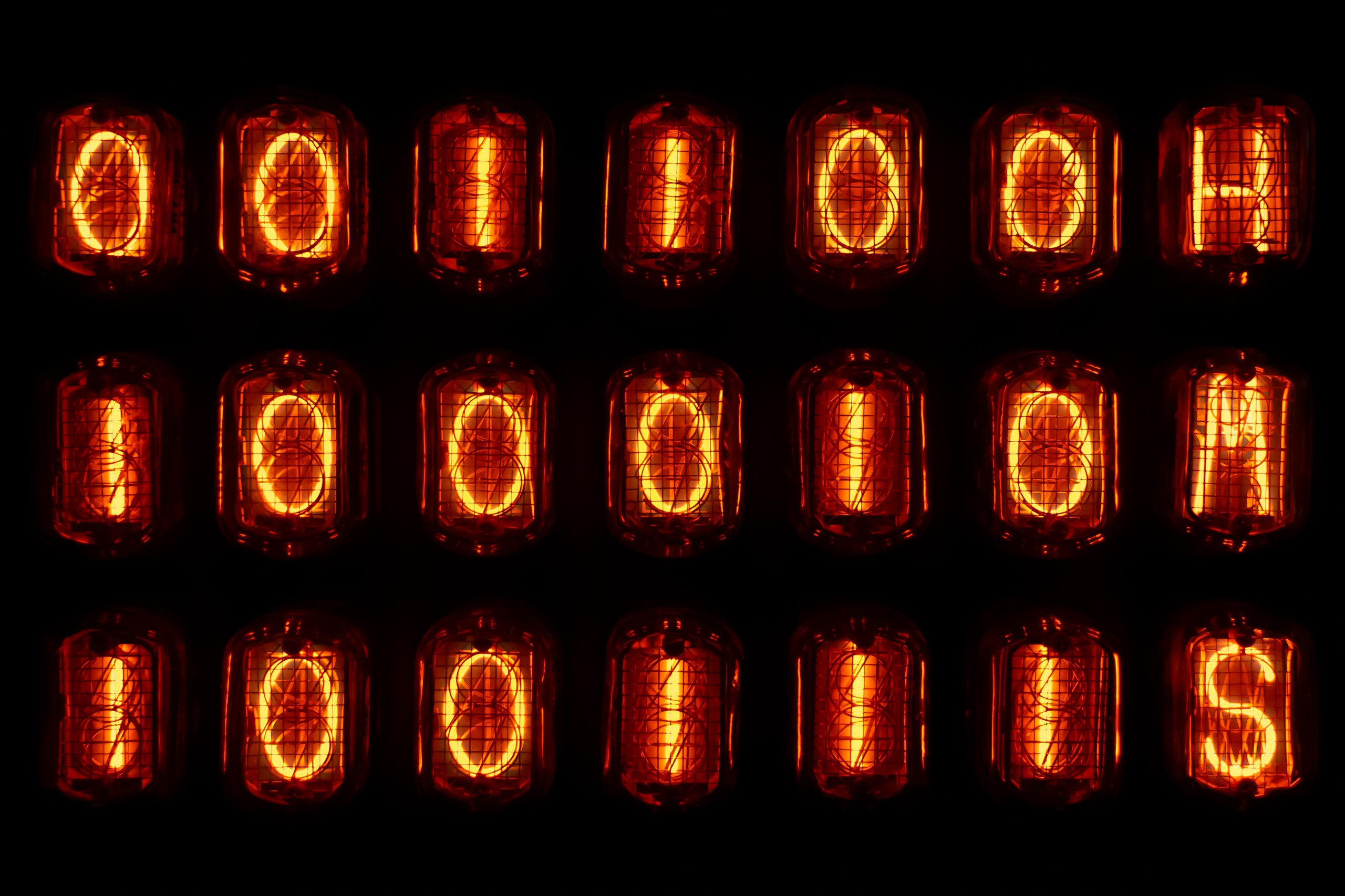
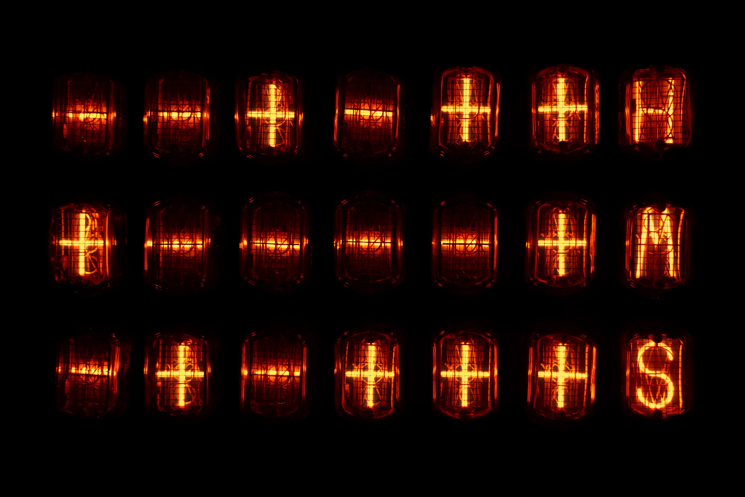
- The time can be displayed with IN-12 (0110) nixie tubes or IN-15A (-++-)
- All tubes are replaceable – pin socket connectors
- RTC real time clock DS3231 module on board
- 2 x Nixie power supply module 170V on board
- 2 x Nixie Tube Driver V2 – on board
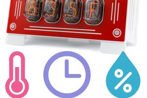
- Designed to work with DHT22/DHT11 temperature & humidity sensor
- Dimensions with tubes: 72 x 160 x 236 mm (~2.8″ x 6.3″ x 9.3″)
- Weight with tubes: 1.1kg (~2.43 lb)
- External power supply required (Arduino VIN connector): 12V; 1.5A DC; plug diameter 2.5 x 5.5 mm; center pin positive+
The clock can be placed e.g. on a desk (power connector on the right side of the housing) or hang on the wall – prepared mounting holes (additional power connector at the bottom of the housing).
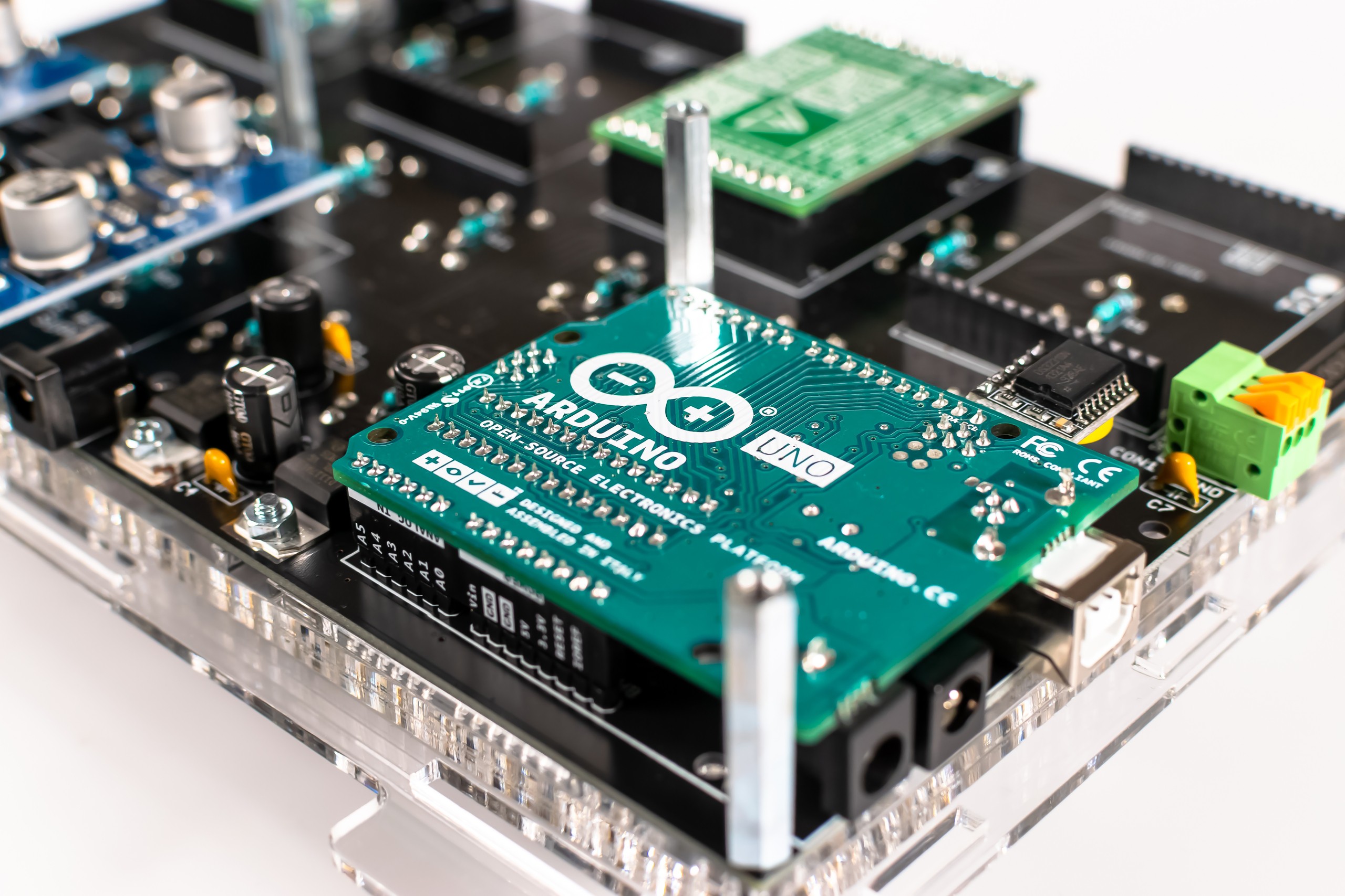
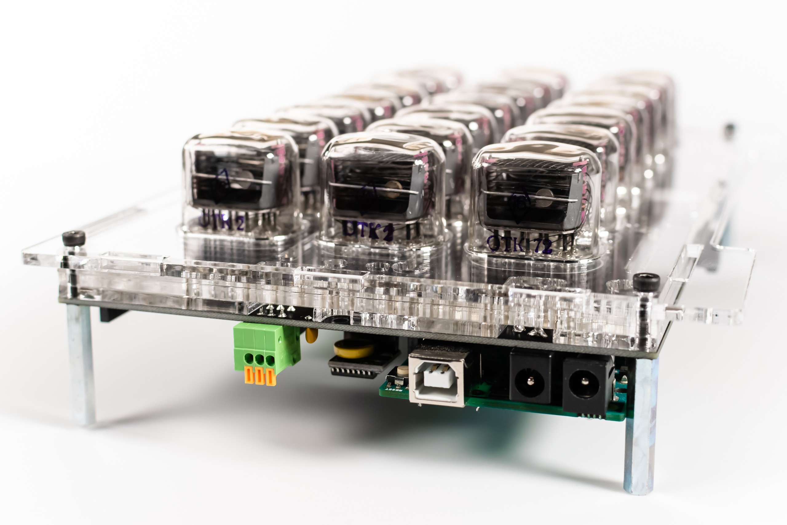
HOW IT'S MADE.
The modular design allows easy and quick assembly. Individual modules are placed in specific slots.
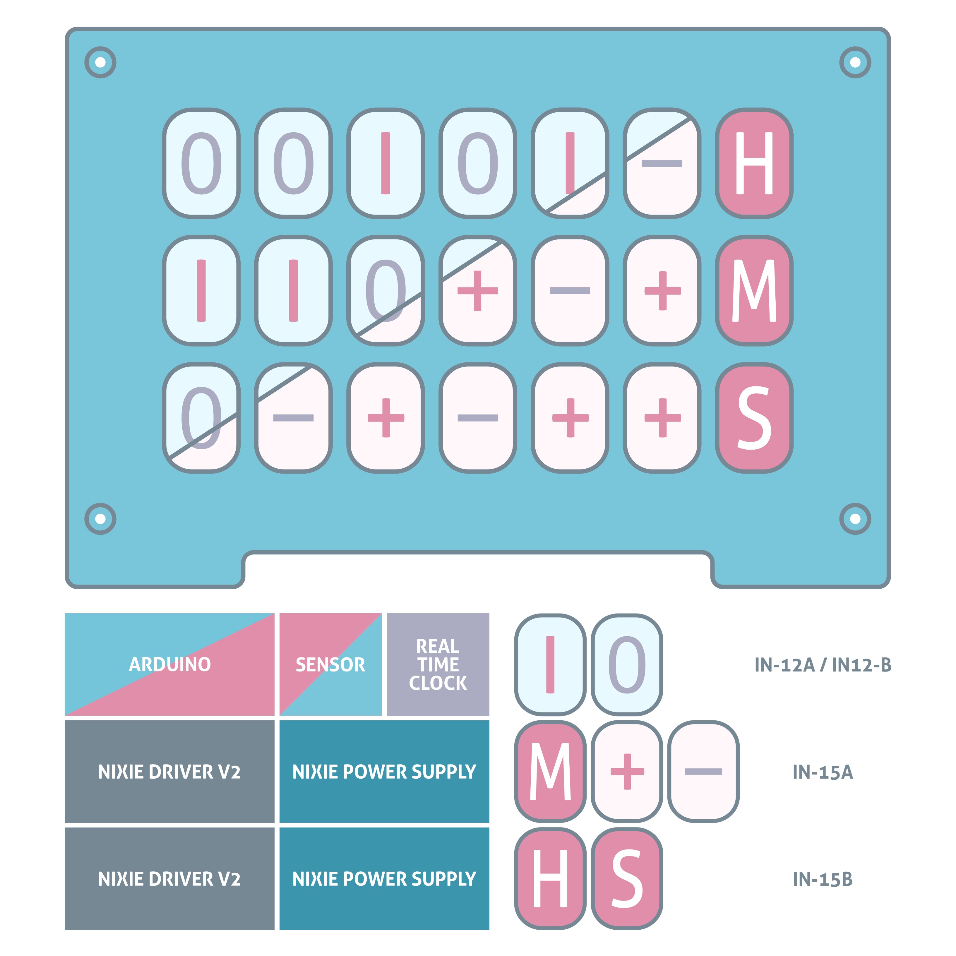
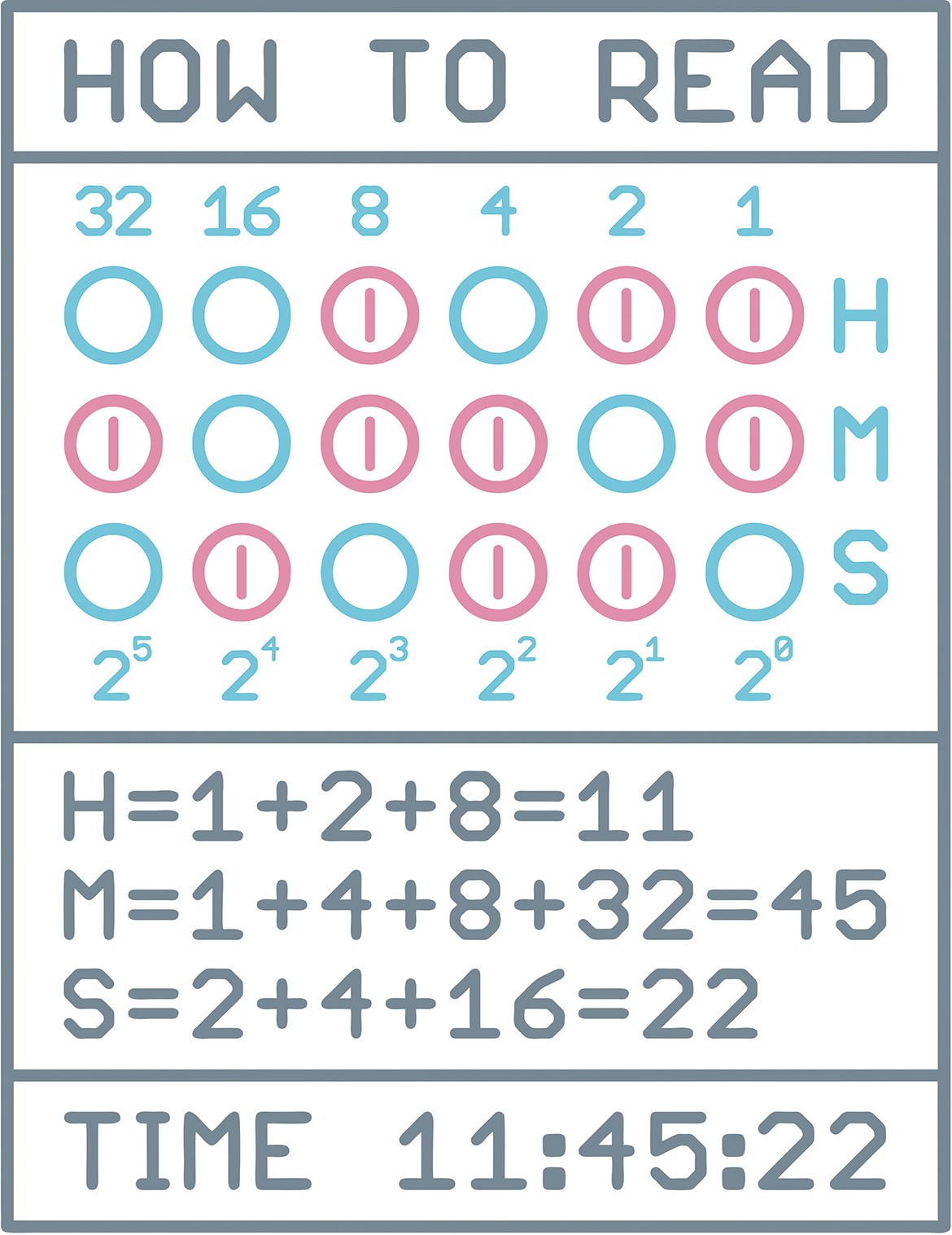
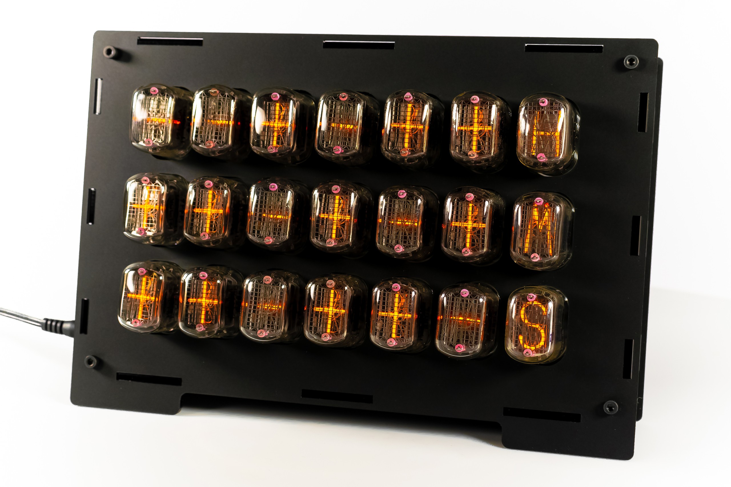
BINARY CODE.
Binary code is a base 2 number system invented by Gottfried Leibniz where numeric values are represented by different combinations of 0 (-) and 1 (+), also know as OFF or ON. Is the simplest form of computer code or programming data.
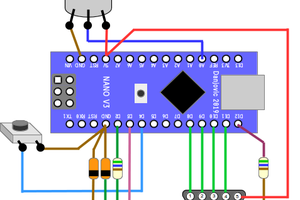
SCHEMATIC.
CODING.
The program code has been prepared:
- Classic Binary Clock – Arduino Uno, Micro, Nano, Nano Every, Nano 33 IoT
- WiFi NTP Binary Clock – Arduino Nano 33 IoT
EASY TO OPERATE.
Just follow the instructions:
- Connect your Arduino board to the Clock
- Download example code
- Connect Shield via USB with your computer
- Connect 12V power supply
- Compile and upload code to the Arduino
- Unplug USB and it’s ready
DATASHEET.
Datasheet can be found on GitHub repository.
CODE EXPAMPLES.
// IN-12 & IN-15 Binary Nixie Clock by Marcin Saj https://nixietester.com
// https://github.com/marcinsaj/IN12-IN15-Binary-Nixie-Clock
//
// Classic IN-12 & IN-15 Binary Nixie Clock Example
//
// This example demonstrates how to set the RTC time, read time from RTC and display on nixie tubes.
// Serial monitor is required to display basic options.
//
// Hardware:
// IN-12 & IN-15 Binary Nixie Clock - https://nixietester.com/project/in12-in15-binary-nixie-clock/
// Arduino Classic e.g. Uno, Leonardo, Zero
// Or Arduino Micro - https://store.arduino.cc/arduino-micro
// Or Arduino Nano - https://store.arduino.cc/arduino-nano
// Or Arduino Nano Every - https://store.arduino.cc/arduino-nano-every
// Or Arduino Nano IoT 33 - https://store.arduino.cc/arduino-nano-33-iot
// 2 x Nixie Power Supply Module, 2 x Nixie Tube Driver V2 & RTC DS3231 module
// Nixie clock require 12V, 1.5A power supply
// Schematic IN-12 & IN-15 Binary Nixie Clock - http://bit.ly/IN12-BNC-Schematic
// Schematic Nixie Tube Driver V2 - http://bit.ly/NTD-Schematic
// Schematic Nixie Power Supply Module - http://bit.ly/NPS-Schematic
// DS3231 RTC datasheet: https://datasheets.maximintegrated.com/en/ds/DS3231.pdf

#include           // https://github.com/adafruit/RTClib

#define EN_NPS    A0
#define DIN_PIN   6          // Nixie driver (shift register) serial data input pin
#define CLK_PIN   7          // Nixie driver clock input pin
#define EN_PIN    8          // Nixie driver enable input pin

// Choose Time Format
#define hourFormat    12     // 12 Hour Clock or 24 Hour Clock

// Bit numbers declaration for nixie tubes display
//            1   2   4   8  16  32
byte H1[] = {40, 42, 15, 17, 19, 21};     // "1" Hours
byte H0[] = {39, 41, 14, 16, 18, 20};     // "0" Hours
byte M1[] = {34, 30, 24, 11,  9,  7};     // "1" Minutes
byte M0[] = {35, 31, 25, 10,  8,  6};     // "0" Minutes
byte S1[] = {32, 28, 26,  5,  3,  1};     // "1" Seconds
byte S0[] = {33, 29, 27,  4,  2,  0};     // "0" Seconds

// 18 bits for "1", 18 bits for "0" - check clock schematic
// 3 bits for "H", "M", "S" symbols
// 5 bits for gaps - nixie drivers not connected outputs
// 2 bits for...
Read more »

 danjovic
 Johan Berglund