Michael Gardi
-
Chess Clocking
02/14/2024 at 21:58 • 2 commentsThe chess clock mode on my CHESSmate Reproduction is now working. It was relatively easy to simulate the 6530-024 Timer by triggering 240 interrupts each minute, which is what the CHESSmate firmware is expecting.
This accounts for the read to 8B0E (the READ TIMER INTERRUPT register) which clears the current interrupt, and the write to 8B0F (the DIV BY 1024 ENABLE INTERRUPTS register) discovered in my Eureka moment.
Number R/W Program Counter Address Value Notes 1 R F390 8B0E Is Timer Interrupt? Occurs when a move is made 2 W F0B2 8B0F F5 Set Interrupt Occurs when move is made Writing F5 to the 8B0F register starts a 250 millisecond timer that will trigger an interrupt when it expires. Once the interrupt has been processed a read to 8B0E will clear the interrupt. When the interrupt service routine processes 240 such interrupts, the minute timer for the current player is incremented by 1. The fractional part, 1/240th of a minute is retained between moves.
Chess clock mode is "stand alone" in that you cannot play chess against CHESSmate when you are chess clocking and vice-versa. You get into chess clock mode by pressing C then ENTER. Pressing H starts WHITE's clock running, then pressing A stops WHITE's clock and start's BLACK's clock. H then switches back to WHITE, then A BLACK and so on. You can press the E key to stop the current clock then E again to restart it.
![]()
Here we see that BLACK is moving and has used up 2 (+)minutes of their clock. When BLACK is done moving they will press H to switch the clock to WHITE. CHESSmate remembers and applies the fractional part of the time used between moves.
-
Eureka!
02/14/2024 at 01:19 • 2 commentsAfter I convinced myself that the emulator was probably OK, I turned back to the ROM. But after I found yet another ROM image online, and it turned out to be identical to the other three, I have to rule out bad ROM as well. Just as well as I was reluctant to put my original CHESSmate at risk.
So that means that my emulation of the CHESSmate hardware must be wrong. However, as far as I could tell, I was handling all of the reads and writes from the firmware. I knew this because I had code in place to detect unhandled I/O. And that would have been a valid assumption if I had put the unhandled code in the right place!
Whoops. Embarrassing. When I relocated the code to the correct spot I discovered that I had missed a few interactions.
Number R/W Program
CounterAddress Value Notes 1 R F390 8B0E Is Timer Interrupt? Occurs when a move is
made2 W F0B2 8B0F F5 Set Interrupt Occurs when move is made 3 R FEF0 8009 Doesn't matter Occurs constantly. Part of the main keyboard / display loop. 4 R F305 8xxx FF Occurs when move made. 5 R F309 8xxx FF Occurs when move made. So what does this mean?
1, 2 - 8B0E and 8B0F are part of the RRIOT Control Registers. I was surprised that I was not picking these up. When I looked at the code I found my second error.
#define RRIOT_REG_SIZE 12There are 16 registers not 12. The 8B0E and 8B0F registers control the RRIOT's Timer. Because of my error, I had not seen these before so I thought that CHESSmate did not use the timer. I was wrong. I did notice that the chess clock feature was not working though. So I fixed the define and am now processing these interactions but will have to spend some time figuring out how they should work. TODO.
3 - I'm not sure exactly what this is doing. It's related to this piece of code:
FEEB 29 7F                AND #$7F
FEED 2C                 .byte $2C       ; BIT skip next instruction
FEEE 09 80       LFEEE    ORA #$80
FEF0 A0 00                LDY #$00      ; lookup conversion
FEF2 8C 00 8B             STY SAD       ; turn off segments
FEF5 8E 02 8B             STX SBD       ; output digit enable
FEF8 8D 00 8B             STA SAD       ; output segments
FEFB E8                   INX
FEFC A0 7F                LDY #$7F      ; delay 500 cycles
FEFE 88         CONVD1    DEY
FEFF D0 FD                BNE CONVD1
FF01 60                   RTS
The 2C 09 80 sequence is treated as a BIT operation on the absolute address 8009. This sets the Negative flag in status to bit-7 of the byte read, and the Overflow flag in status to bit-6 of the byte read. Since there are no subsequent branch instructions I'm pretty sure this sequence has no effect on the code. This looks like a patch of some sort. Ignored.
4, 5 - These occur when a move is being made. The address is in the 8xxx range but varies quite a bit. They are associated with this piece of code.
F303 B1 76       LF303     LDA ($76),Y
F305 48                    PHA
F306 C8                    INY
F307 B1 76                 LDA ($76),Y
F309 85 2A                 STA $2A
F30B 68                    PLA
F30C A2 11                 LDX #$11
So I do the sequence H - ENTER (switch CHESSmate to WHITE), G - ENTER (CHESSmate MOVES). If I return a 0 to these two reads CHESSmate fails returning the move H1 - H1. If I return FF to the reads, CHESSmate plays E2 - E4, the same as the original game. I think that this has something to do with the opening book. I'll have to dig in a bit to figure it out. TODO
The bottom line here is that with these changes the game plays pretty well now. I played a couple of full games today with no issues, from the opening move to the annoying musical sequence CHESSmate plays when it wins (both games sigh).
I still have some work to do but I'm much more confident now of a great result.
-
Hardware Good, Software Not So Much
02/12/2024 at 19:40 • 0 commentsWhile I continue to try and determine what's up with my CHESSmate firmware, I'm forging ahead with the hardware.
Hardware
I'm reasonably certain that the CHESSmate PCB and ESP-32 are working as expected from an electronics perspective. So to that end | have designed a daughter board to attach the ESP-32 to the back of the main board via the 22-pin header.
![]()
The idea is that the daughter board will have a 90 degree female header underneath and facing "inwards" to connect with the existing male header on the PCB like a little "back pack". My original thought was to redo the PCB and add the ESP-32 to the board itself, like Oscar Vermeulen did with his KIM Uno project. In the end I decided this way was more flexible, especially if I (or someone else) ends up doing a 6502 based hardware "back pack".
Software
On the software side I have tried a few time to play a game through on my reproduction. At first everything seems to be going great. But after five or six moves CHESSmate signals that a move I have made is invalid even when I know it's a good move. There is an option to check the positions of all the pieces on the board (B - ENTER) and when I do this I find that CHESSmate has lost track of one or two of the pieces. Sigh. I have the hardware now to dump the ROM from my original CHESSmate. I sure hope that is the problem because if the ROM is not different from the ones I download I'm not sure where to go next.
-
99% Sure It's Not an Emulator Bug
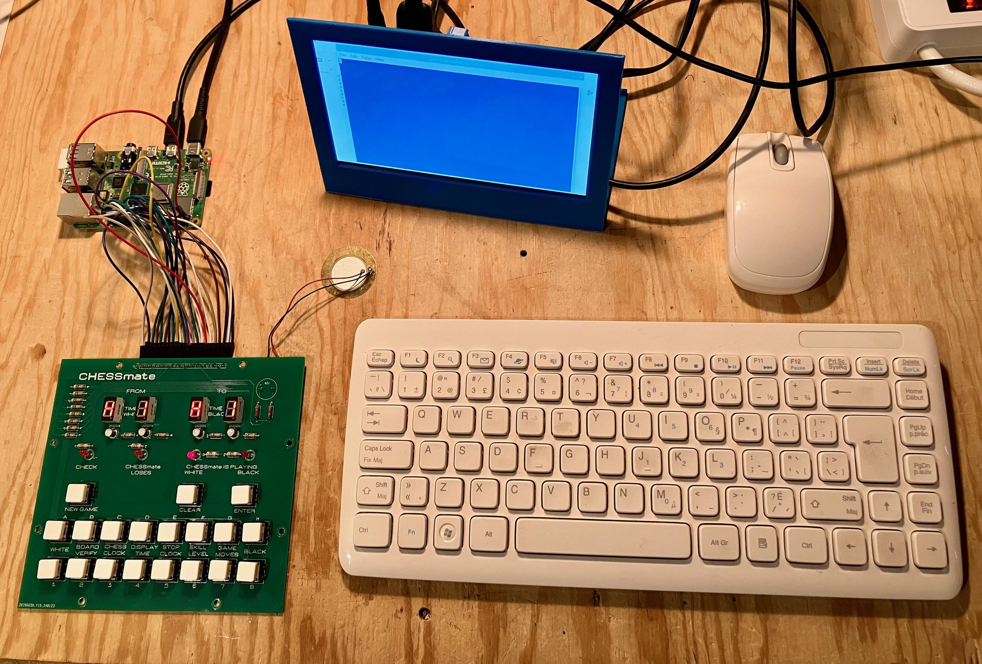
02/08/2024 at 17:53 • 0 commentsI ported the CHESSmate code to a Raspberry Pi 4 running under a Python based 6502 emulator. One thing that I learned doing this is that this emulator runs way to slow to be a viable option. Perhaps a C based 6502 emulator running on the Pi would fare better.
![]()
To my surprise, CHESSmate exhibited exactly the same errant behavior as it did running on the ESP32 and the Arduino Pro Mini. So there is no way that these glitches are a result of a misbehaving emulator.
So I guess I'm back to bad ROM images. I guess I'll have to dump the original CHESSmate ROM to know for sure.
-
Okay, Houston, we've had a problem here.
02/07/2024 at 16:51 • 0 commentsJust when I thought I was heading into the home stretch I noticed something not so good. I had the CHESSmate manual out and was trying some of the various settings. One thing I tried was setting my CHESSmate reproduction to play white and have "it" make the first move to which it returned H1 - H1. What? That sure doesn't look right. The original plays C2 - C4. Similarly when I play white and make the conventional E2 - E4 kings pawn opening, the reproduction plays D7 - D5, while the original plays E7 - E5. Crap.
My first though was that maybe the ROM that I downloaded was somehow corrupt. Since I have an original, I could, with some effort, get a fresh ROM image from it (even though I'd be a little apprehensive doing so given its rarity). So before I tried that I found two additional images. One was described as being another Commodore CHESSmate ROM, but the other was for a Novag Chess Champion Mk II, clearly a CHESSmate clone. All three images were identical! So not likely the ROM.
That only leaves a couple of alternatives.
- My interface between the Sketch and the emulator is somehow incorrect. I find this hard to believe. I'm just mapping physical memory to the addresses that the CHESSmate firmware is expecting. If this interface were wrong the program would more than likely crash. Instead it runs fine processing millions of instructions.
- Unfortunately that leaves (in my mind) only one other alternative, there is a subtle underlying problem with the 6502 emulator.
OK, emulator issue. The first thing I did was to review what I had done to get the emulator working. Oscar Vermeulen had made extensive changes to Mike Chambers' code in order to get all of the cool features working in KIM Uno like Microchess, Programmable Calculator, KIM utilities, etc.. I had decided to start with a fresh copy of Mike's code because it would be less confusing. I went back and looked at Oscar's code and found that he had applied a "BCD fix" to the emulator. Ah ha! That must be it! Unfortunately it was not. I applied the same fix and no joy. Same problem.
One thought I have as to why this issue did not crop up in KIM Uno running Microchess is that for CHESSmate Peter Jennings added "32 International standard openings in its memory and tries to follow them for 16 moves". The bug could be triggered by the new openings code.
I had a similar issue with my Sol-20 Reproduction. Everything seemed to be working (games, utilities, monitor, etc.), but when I tried to run BASIC (two different versions) it would fail. Now that was for an 8080 emulator, but I eventually found the problem by running test suites against the emulator until something broke. As I recall it was an obscure half-carry flag DAA instruction issue (also BCD related - coincidence?).
For my Challenger 4P Reproduction I used a 6502 Python based emulator running on a Raspberry Pi 4. This got me thinking that It would not take me very long to move CHESSmate over to a Pi. If it works, I know for sure that the issue on the ESP32 is emulator related. If not I can begin the tedious task of trying to find the emulator bug. OK that's the new plan.
-
Much Better
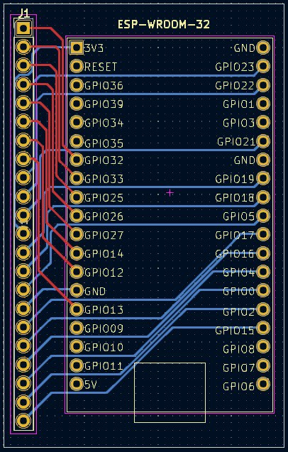
02/05/2024 at 23:04 • 0 commentsI was not able to improve the performance of CHESSmate much on the Arduino Pro Mini so I purchased an ESP32 ESP-WROOM-32 NodeMCU Development Board.
By sticking with the Arduino IDE it was relatively easy to port the code to the new device. Harder was finding a set of IO pins that did not conflict with internal ESP32 restrictions that are not always obvious. The ESP32 has a lot of pins that are billed as general purpose IO (GPIO), but there are many subtle caveats, like for instance:
Pins GPIO34, GPIO35, GPIO36(VP) and GPIO39(VN) cannot be configured as outputs. They can be used as digital or analog inputs, or for other purposes. They also lack internal pull-up and pull-down resistors, unlike the other GPIO pins.
At any rate I was able to find the 19 IO pins I needed. The compiled code runs much better on the ESP32, not surprising given that the CPU frequency can be set as high as 240 MHz. I actually found that running at 240 MHz was too fast. The code ran fine, but the sound effects in particular were just high pitched chirps of noise. Running at a sedate 80 MHz gives the most authentic user experience running at almost exactly the same speed at the original.
I have added to new code to GitHub.
So I am going to move ahead with the ESP32 version. From a cost point of view we are talking $10 for the ESP32 vs $3 for an Arduino Pro Mini. Not a big deal. Plus I have plans for the built-in Wi-Fi for a future "redux" version of CHESSmate.
Here is how CHESSmate runs on the ESP32.
One thing you might notice is the dim PLAYING BLACK LED. Since the ESP32 is running at 3.3V vs 5V for the Arduino, I'll have to rework the resistor values for the next version. For the current version I just swapped in some high brightness LEDs which did the trick.
-
Success"ish"
02/03/2024 at 17:39 • 2 commentsGetting the CHESSmate emulator running was relatively straight forward, but "the devil's in the details" as they say. Took me a couple of days, partly because I had to figure out how the CHESSmate program was interacting with the original hardware, and partly because of my own silly mistakes.
Changes To The 6502 Emulator
I started by cloning Mike Chambers excellent 6502 emulator for Arduino. The code comes pre-configured to run EhBASIC, so I used this example to set up the emulator to run CHESSmate. For the most part all you have to do is define the blocks of RAM and ROM that the program requires to run. Here is the relevant code from cpu.c.
// Callbacks to the CHESSmate sketch.
extern uint8_t readRRIOT(uint16_t address);
extern void writeRRIOT(uint16_t address, uint8_t value);

...

// Addresses and sizes of the various memory locations CHESSmate is expecting.
#define CHESSMATE_ROM 0xF000
#define RRIOT_REGISTERS 0x8B00
#define RRIOT_RAM_ADDR 0x8B80

#define RAM_SIZE 1536
#define ROM_SIZE 4096
#define RRIOT_REG_SIZE 12
#define RRIOT_RAM_SIZE 64

...

// Allocate space for the the expected memory locations starting with main RAM.
uint8_t RAM[RAM_SIZE];

// This is the original CHESSmate ROM.
PGM_P const CHESSMATE[ROM_SIZE] PROGMEM = {
    0xd8,0x58,0xa2,0xfe,0x9a,0xa9,0x3f,0x8d,0x03,0x8b,0xa9,0xff,0xa2,0x00,0x95,0x00,
0xd5,0x00,0xf0,0x05,0xb5,0x00,0x4c,0x14,0xf0,0xca,0xd0,0xf2,0x49,0xff,0xf0,0xee,
0xa9,0x05,0x85,0x53,0xa2,0x21,0xbd,0x52,0xfe,0x95,0x00,0xca,0x10,0xf8,0x86,0x59,
... // many lines omitted
0x53,0x00,0x00,0x40,0x08,0x40,0x3f,0x06,0x5b,0x4f,0x66,0x6d,0x7d,0x07,0x7f,0x6f,
0x53,0x00,0x00,0x40,0x08,0x00,0x00,0x00,0x43,0x48,0x45,0x53,0x53,0x4d,0x41,0x54,
0x45,0x20,0x37,0x2e,0x35,0x00,0x00,0x00,0x00,0x00,0x00,0x00,0x00,0xf0,0x4c,0xf3
};

// The 6520-24 RIOT chip on the original CHESSmate had 64 bytes of RAM.
uint8_t RRIOT_RAM[RRIOT_RAM_SIZE];

// Whenever the emulator needs to grab a byte from memory this function gets
// called. Based on the address passed, it returns the byte from the appropriate
// memory block.
uint8_t read6502(uint16_t address) {
  uint16_t PGMaddr;

  // Main program.
  if (address >= CHESSMATE_ROM) {
    PGMaddr = address - CHESSMATE_ROM;
      return(pgm_read_byte_near(CHESSMATE + PGMaddr));
  }

  // RAM memory.
  if (address < RAM_SIZE) return(RAM[address]);

 // RRIOT RAM memory.
  if (address >= RRIOT_RAM_ADDR && address < (RRIOT_RAM_ADDR + RRIOT_RAM_SIZE)) {
      PGMaddr = address - RRIOT_RAM_ADDR;
      return(RRIOT_RAM[PGMaddr]);
  }

  // The 6530-24 chip was controlled by a few memory mapped RRIOT registers.
  // In this case we will call back to the CHESSmate script to fetch the appropriate
  // byte.
  if (address >= RRIOT_REGISTERS && address < (RRIOT_REGISTERS + RRIOT_REG_SIZE)) {
      PGMaddr = address - RRIOT_REGISTERS;
      return readRRIOT(PGMaddr); [NOTE 1]
  }

  // Not a valid memory location.
  return(0);
}

// Whenever the emulator needs to write a byte to memory this function gets
// called. Based on the address passed, it writes the byte to the appropriate
// memory block.
void write6502(uint16_t address, uint8_t value) {
  uint16_t PGMaddr;

  // RAM memory.
  if (address < RAM_SIZE) RAM[address] = value;

  // RRIOT RAM memory.
  if (address >= RRIOT_RAM_ADDR && address < (RRIOT_RAM_ADDR + RRIOT_RAM_SIZE)) {
        PGMaddr = address - RRIOT_RAM_ADDR;
      RRIOT_RAM[PGMaddr] = value;
  }

  // The 6530-24 chip was controlled by a few memory mapped RRIOT registers.
  // In this case we will  call back to the CHESSmate script to "write" the
  // appropriate byte.
  if (address >= RRIOT_REGISTERS && address < (RRIOT_REGISTERS + RRIOT_REG_SIZE)) {
      PGMaddr = address - RRIOT_REGISTERS;
      writeRRIOT(PGMaddr, value);
  }
}

...


[NOTE 1] - This was one of my mistakes. For a while I was making the call
           to readRRIOT and not returning the result. Doh.
The hardware components on the original CHESSmate (LEDs, 7-segment displays, and keys) were controlled by a 6530-24 RRIOT chip which stands for ROM RAM I/O and Timer. Given that one of the features of CHESSmate is a chess clock, I was surprised that the program did not take advantage of the Timer function of the chip, only the RAM and I/O.
The I/0 feature consisted of 16 lines that can be configured as either Input or Output grouped into 2 "ports" A and B. There are four 8-bit registers on the 6530-24 that control these I/O lines.
Port Name Memory Mapped Address Description SAD 0x8B00 Port A Data PADD 0x8B01 Port A Data Direction SBD 0x8B02 Port B Data PBDD 0x8B03 Port B Data Direction On the original CHESSmate these 16 lines are connected to the LEDs, switches, and 7-segment display. The 8 lines of the A Port were cleverly used to both read keys and update the 7- segment display segments. Cool.
Pretending To Be A 6530-24
In the CHESSmate Arduino sketch I process the callbacks and map the calls to and from the RRIOT "registers" to the actual hardware of my implementation. This is what the relevant code looks like.
/********************************************************************************************
   *   This is the key part of the CHESSmate "emulation". Pretend to be a 6530-24 RRIOT chip.
   *
   *   Translate the reads and writes to and from the program to the 6530-24 RRIOT registers
   *   and map the bits to the actual switches, 7-segment displays, and LEDs.
   *
   ********************************************************************************************/
  // Handle reads from RRIOT registers.
  uint8_t readRRIOT(uint16_t address) {
    if (address == 2) {             // Port B Data
      // Reading from PORTB. Return the previous value of PORTB.
      return sbc_value;
    } else if (address == 0) {      // Port A Data
      // Check for NEW GAME. (Reset)
      if (digitalRead(NEW_GAME_KEY) == LOW) {
        reset6502();
      }
      // Check for keypresses. Default result, no keys pressed.
      uint8_t result = 0b01111111; [NOTE 2]

      // On the original there were 2 rows when reading the keyboard.
      if (keyboard_row == 1) {
        if (digitalRead(PA7) == LOW) {
          result = 0b01011111;
        } else if (digitalRead(PA6) == LOW) {
          result = 0b01101111;
        } else if (digitalRead(PA5) == LOW) {
          result = 0b01110111;
        } else if (digitalRead(PA4) == LOW) {
          result = 0b01111011;
        } else if (digitalRead(PA3) == LOW) {
          result = 0b01111101;
        } else if (digitalRead(PA2) == LOW) {
          result = 0b01111110;
        }
      } else if (keyboard_row == 2) {
        if (digitalRead(PA1) == LOW) {
          result = 0b00111111;
        } else if (digitalRead(PA0) == LOW) {
          result = 0b01011111;
        } else if (digitalRead(CLEAR_KEY) == LOW) {
          result = 0b01101111;
        } else if (digitalRead(ENTER_KEY) == LOW) {
          result = 0b01110111;
        }
      }
      return result;
    }
  }

  // Handle writes to RRIOT registers.
  void writeRRIOT(uint16_t address, uint8_t value) {
    if (address == 0) {                 // Port A Data
      // PA0 - PA7 Data Register (SAD)
      // Maps to Pro Mini pins 0 - 7. Have to invert for my hardware.
      PORTD = ((lookup[value & 0b1111] << 4) | lookup[value >> 4]) & 0xFE;

      // Check for CHESSmate LOSES.
      if ((value & 0b10000000) > 0) {
        digitalWrite(LOSES_LED, HIGH);
      } else {
        digitalWrite(LOSES_LED, LOW);
      }
    } else if (address == 1) {          // Port A Data Direction
      // PA0 - PA7 Data Direction Register (PADD)
      if (value == 128) {
        PORTD = 0x00;     // All inputs.
        PORTD |= 0xFF;    // Input pullups.
      } else {
        DDRD = value;     // All outputs.
      }
    } else if (address == 2) {          // Port B Data
      // PB0 - PB7 Data Register (SBD)
      // Remember the last value written to this register.
      sbc_value = value;

      // The bottom 3 bits of the value control 8 IO lines.
      // Only 1 of the 8 will be turned on. Start with everything off.
      digitalWrite(DISPLAY_1, LOW);
      digitalWrite(DISPLAY_2, LOW);
      digitalWrite(DISPLAY_3, LOW);
      digitalWrite(DISPLAY_4, LOW);
      keyboard_row = 0;
      digitalWrite(BUZZER_1, LOW);
      digitalWrite(BUZZER_2, LOW);

      // Determine which line to enable.
      switch (value & 0x07) {
        case 0:
          digitalWrite(DISPLAY_1, HIGH);
          break;
        case 1:
          digitalWrite(DISPLAY_2, HIGH);
          break;
        case 2:
          digitalWrite(DISPLAY_3, HIGH);
          break;
        case 3:
          digitalWrite(DISPLAY_4, HIGH);
          break;
        case 4:
          keyboard_row = 1;
          break;
        case 5:
          keyboard_row = 2;
          break;
        case 6:
          digitalWrite(BUZZER_1, HIGH);
          break;
        case 7:
          digitalWrite(BUZZER_2, HIGH);
          break;
        default:
          break;
      }
      // Check for CHECK LED.
      if ((value & 0b00001000) > 0) {
        digitalWrite(CHECK_LED, HIGH);
      } else {
        digitalWrite(CHECK_LED, LOW);
      }
      // Check for BLACK or WHITE LED.
      if ((value & 0b00010000) > 0) {
        digitalWrite(B_W_LED, LOW);
      } else {
        digitalWrite(B_W_LED, HIGH);
      }
    } else if (address == 3) {            // Port B Data Direction
      // PB0 - PB7 Data Direction Register (PBDD)
      // Does not directly map to specific pins. Will always be 0x7F.
    }
  }
}

[NOTE 2] - It took me a while to clue into the fact that the program was
           expecting the key pressed bit to be a 0 and all other bits 1.
           Dusting off my 6502 assembler and looking at the code helped me
           to figure this out
So the updated working code has been posted to GitHub.
And Now For The "ish" Part
Better if I just show you.
So the emulator is running. When I uploaded the file, YouTube apparently muted the piezo speaker audio which sounds just terrible if you listen closely. This is because the application is running about 8 times slower under the emulator than the original. Disappointing since I was given to understand that the emulator, when used with the KIM-1 Uno and Pro Micro, ran pretty well. I'll have to take a look at Oscar's code to see if somehow I have introduced a bunch of overhead in my code.
In the mean time I just got all of the parts to build a KIM-1 Uno which I have been meaning to do for a while now. That way I'll have something concrete to compare against.
I have also ordered a few ESP32s in case I have to throw more horsepower at the problem.
-
Testing The CHESSmate PCB
01/31/2024 at 17:08 • 0 commentsWell the PCBs arrived and I wanted to make sure all of the active components were working, so populated the board and extended my quick and dirty test program.
#define PA0  7
#define PA1  6
#define PA2  5
#define PA3  4
#define PA4  3
#define PA5  2
#define PA6  1
#define PA7  0

#define ENTER_KEY     8
#define CLEAR_KEY     9
#define NEW_GAME_KEY  10

#define CHECK_LED 11
#define LOSES_LED 12
#define B_W_LED 13

#define DISPLAY_1     A0
#define DISPLAY_2     A1
#define DISPLAY_3     A2
#define DISPLAY_4     A3

#define BUZZER_1      A4
#define BUZZER_2      A5

void setup()
{
   // define pin modes
   pinMode(PA0,OUTPUT);
   pinMode(PA1,OUTPUT);
   pinMode(PA2,OUTPUT);
   pinMode(PA3,OUTPUT);
   pinMode(PA4,OUTPUT);
   pinMode(PA5,OUTPUT);
   pinMode(PA6,OUTPUT);
   pinMode(PA7,OUTPUT);
   pinMode(CHECK_LED,OUTPUT);
   pinMode(LOSES_LED,OUTPUT);
   pinMode(B_W_LED,OUTPUT);

   pinMode(DISPLAY_1,OUTPUT);
   pinMode(DISPLAY_2,OUTPUT);
   pinMode(DISPLAY_3,OUTPUT);
   pinMode(DISPLAY_4,OUTPUT);

   pinMode(BUZZER_1,OUTPUT);
   pinMode(BUZZER_2,OUTPUT);

   pinMode(ENTER_KEY,INPUT_PULLUP);
   pinMode(CLEAR_KEY,INPUT_PULLUP);
   pinMode(NEW_GAME_KEY,INPUT_PULLUP);
}


void loop()
{
  // loop to turn display segments ON one at a time
  digitalWrite(DISPLAY_1,HIGH);
  for(int i=0; i<8; i++) {
    digitalWrite(7-i,HIGH);
    delay(600);
  }

  // loop to blink display
  for(int i=0; i<5; i++)
  {
    if (i%2) {
      digitalWrite(DISPLAY_1,HIGH);
      digitalWrite(B_W_LED,LOW);
    } else {
      digitalWrite(DISPLAY_1,LOW);
      digitalWrite(B_W_LED,HIGH);
    }
   delay(600);
  }

  // Test the other LEDS.
  digitalWrite(CHECK_LED,HIGH);
  delay(500);
  digitalWrite(LOSES_LED,HIGH);
  delay(500);
  digitalWrite(CHECK_LED,LOW);
  digitalWrite(LOSES_LED,LOW);
  delay(500);

  // Test the other displays.
  digitalWrite(DISPLAY_1,LOW);
  digitalWrite(DISPLAY_2,HIGH);
  delay(500);

  digitalWrite(DISPLAY_2,LOW);
  digitalWrite(DISPLAY_3,HIGH);
  delay(500);

  digitalWrite(DISPLAY_3,LOW);
  digitalWrite(DISPLAY_4,HIGH);
  delay(500);

  digitalWrite(DISPLAY_1,HIGH);
  digitalWrite(DISPLAY_2,HIGH);
  digitalWrite(DISPLAY_3,HIGH);
  delay(500);

  digitalWrite(DISPLAY_2,LOW);
  digitalWrite(DISPLAY_3,LOW);
  digitalWrite(DISPLAY_4,LOW);
  delay(500);

  // Make a tone manually. Half Bridge.
  for(int i=0; i<1000; i++)
  {
      digitalWrite(BUZZER_1, LOW);
      delay(1);
      digitalWrite(BUZZER_1, HIGH);
      delay(1);
  }
  delay(500);

  // Make a tone manually. Full Bridge.
  for(int i=0; i<1000; i++)
  {
      digitalWrite(BUZZER_1, LOW);
      digitalWrite(BUZZER_2, HIGH);
      delay(1);
      digitalWrite(BUZZER_1, HIGH);
      digitalWrite(BUZZER_2, LOW);
      delay(1);
  }

  // loop to turn display segments OFF
  for(int i=0;i<8;i++)
  {
    digitalWrite(i,LOW);
  }

  // Test the NEW GAME button.
  while (digitalRead(NEW_GAME_KEY) == HIGH) {
    delay(100);
  }
}
And the results were good.
So now all I have to do is make the Arduino Pro Mini pretend to be a 6504 processor running the CHESSmate code and interfacing with the front panel hardware. Piece of cake ;-)
-
Testing The CHESSmate PCB Circuits
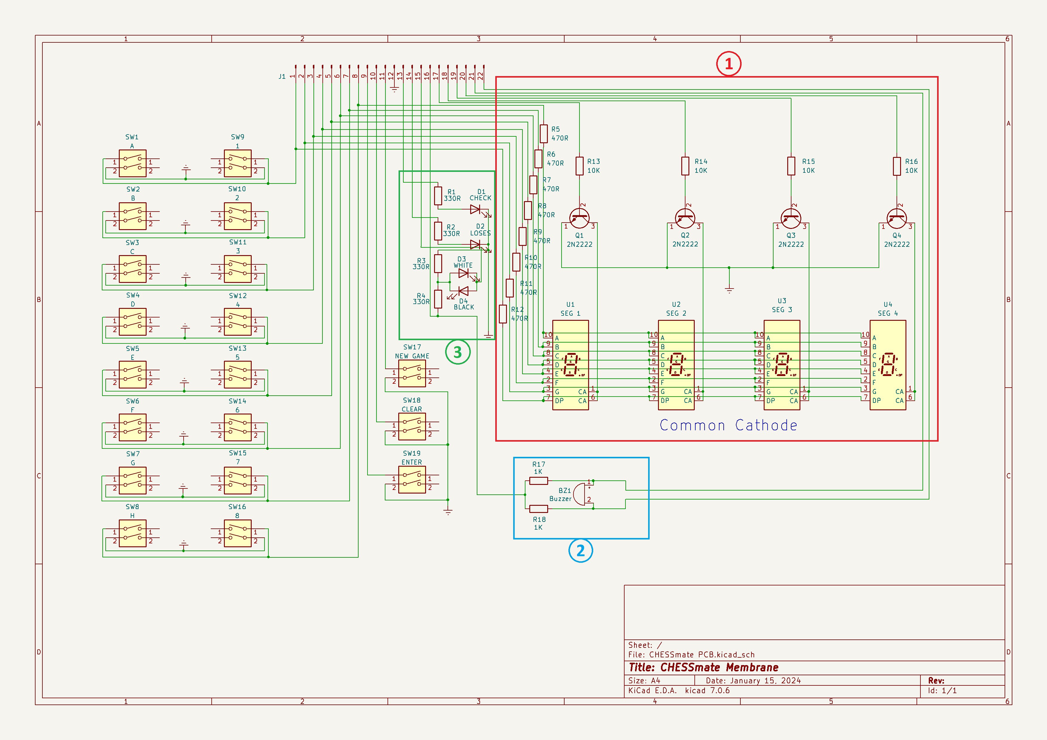
01/23/2024 at 18:59 • 0 commentsBefore sending the PCB off for fabrication I wanted to do a sanity check on some of the circuits I had laid out. For instance I wanted to make sure that I had the common cathode 7-segment displays wired properly (see 1 below) and that the 470R limiting resistors provided a fairly bright display since they would be dimmed somewhat when multiplexed.
![]()
I was a bit perplexed by piezo buzzer circuit (2 above). Why use two IO pins when one will do? One of my makerspace (Kwartzlab) mates pointed out that the circuit reminded them of a full bridge motor controller. Sure enough further research revealed the magic of a full bridge piezo driver.
From the adafruit forum:
If you connect the Piezo between two of the Arduino's pins and control them so one goes high the same time the other goes low, you'll get what's called 'bridged' drive. That effectively doubles the voltage across the piezo element, making it louder.
Works a treat.
In order to free up a pin that I needed to get me to the 20-pin limit that the Arduino Pro Mini I will be using provides, I put the "Plays White" and "Plays Black" LEDs on a single pin (3 above) since they will always be the inverse of each other anyway (as does the original CHESSmate). I wanted to make sure that the circuit works and that the brightness of the two LEDs remains even.
I breadboarded these circuits and wrote a small quick and dirty sketch to exercise them.
void setup()
{
  // define pin modes

 pinMode(2,OUTPUT);  // 7-segment data
 pinMode(3,OUTPUT);
 pinMode(4,OUTPUT);
 pinMode(5,OUTPUT);
 pinMode(6,OUTPUT);
 pinMode(7,OUTPUT);
 pinMode(8,OUTPUT);
 pinMode(9,OUTPUT);
 pinMode(10,OUTPUT);  // 7-segment select
 pinMode(16,OUTPUT);  // // white / black LEDs
 pinMode(15,OUTPUT);  // Buzzer pins
 pinMode(14,OUTPUT);

 digitalWrite(16,HIGH);
}

void loop()
{
  // loop to turn display segments ON one at a time
  digitalWrite(10,HIGH);
  for(int i=2;i<10;i++)
  {
    digitalWrite(i,HIGH);
    delay(600);
  }

  // loop to blink display and alternate LEDs
  for(int i=0; i<10; i++)
  {
    if (i%2) {
      digitalWrite(10,HIGH);
      digitalWrite(16,LOW);
    } else {
      digitalWrite(10,LOW);
      digitalWrite(16,HIGH);
    }
   delay(600);
  }


  // Make a tone manually. Half Bridge.
  for(int i=0; i<1000; i++)
  {
      digitalWrite(14, LOW);
      // digitalWrite(15, HIGH);
      delay(1);
      digitalWrite(14, HIGH);
      // digitalWrite(15, LOW);
      delay(1);
  }
  delay(500);

  // Make a tone manually. Full Bridge.
  for(int i=0; i<1000; i++)
  {
      digitalWrite(14, LOW);
      digitalWrite(15, HIGH);
      delay(1);
      digitalWrite(14, HIGH);
      digitalWrite(15, LOW);
      delay(1);
  }

  // loop to turn display segments OFF
  for(int i=2;i<10;i++)
  {
    digitalWrite(i,LOW);
  }
}
Here is what running the test looks like.
The 7-segment display works as expected and is plenty bright. White and black LEDs alternate correctly and appear to be of even brightness. The first tone at the end is the piezo being run with only one output (half bridge) and the second tone with two outputs (full bridge) and is noticeably louder.
With these tests under my belt I sent the PCB off to be fabricated.
-
3Ding the PCBing
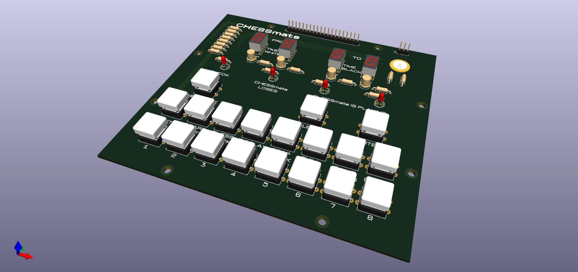
01/20/2024 at 23:52 • 0 commentsI spent the day going over my PCB design, and am beginning to feel more confident about it. As part of this exercise I played around with KiCad's 3D modelling feature. I have to say I'm very impressed.
![]()
The KiCad library of generic 3D parts it pretty good, but I still had to search around a bit for models with a closer match to the components I will be using, especially in my case the push button switches. Fortunately it's relatively easy to modify the footprint libraries to use these found 3D models. Very cool.
Aside from looking cool how does this help me? Well it turns out that this 3D model can be exported from KiCad as a .step file. This in turn can be imported into Fusion 360. How does this help? Lets see.
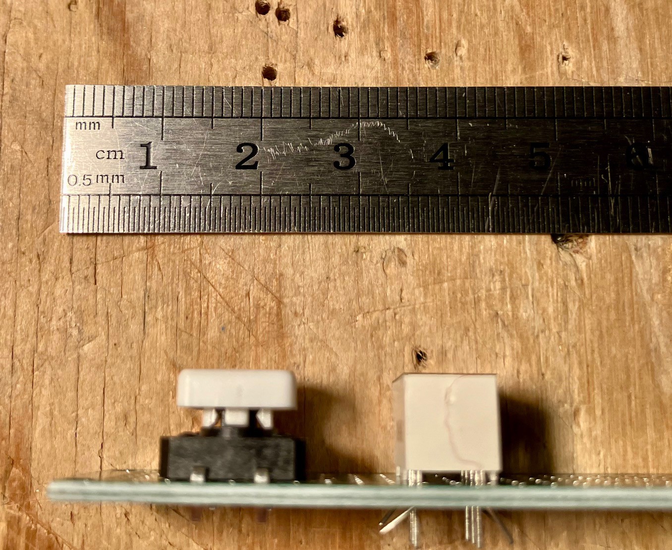
When I popped one of my 7-segment displays and a push button into a project board, I noticed that I had gotten a bit lucky with my choices.
![]()
The push button is about a millimeter or two taller than the 7-segment display. This is perfect for my purposes because I want the membrane to lay on top of all the buttons, LEDs, and displays. Being slightly taller will allow the button to be more easily pressed.
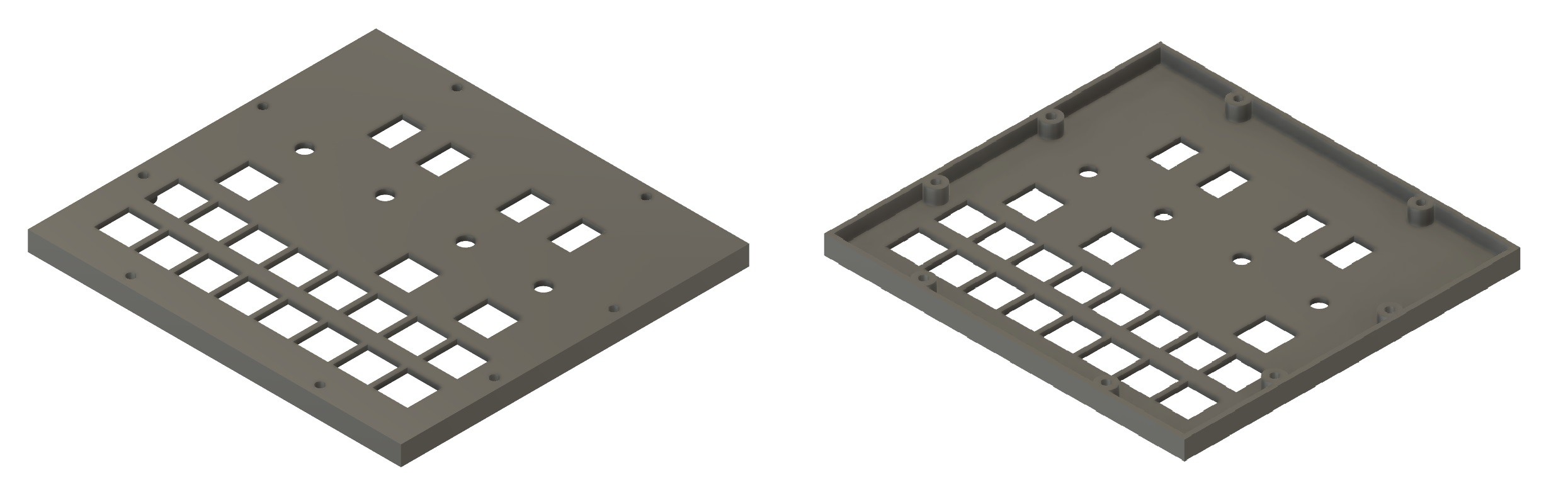
In order to better support the membrane I will be printing a standoff with cutouts for the displays, LEDs, and buttons. By measuring the height of the 7-segment display relative to the PCB I know that this standoff needs to be 9 mm tall.
![]()
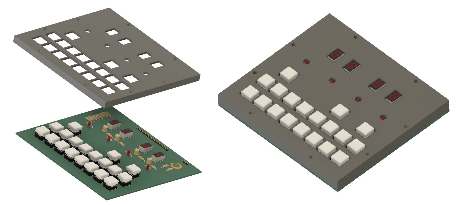
Before I have even sent the PCB design to the fabricator, I can validate that the standoff cutouts are correct by bringing the 3D PCB model into Fusion 360 and aligning it with the standoff.
![]()
Now the 3D button model of the switch that I found for the PCB is actually a little taller than the actual, so it protrudes in the image above more that it will in practice, but the switch cap is correctly sized at 12 mm x 12 mm, so I can see that the alignment of the cutouts appear to be accurate. Nice.
Commodore CHESSmate Reproduction
The plan is to make a reproduction of the dedicated chess computer CHESSmate released by Commodore in 1978.