 BaumInventions
After we understood the protocol it is time to have a look at the content of a display message.

You should be familiar with Hexadecimal to properly follow this Blog.
To not make it more confusing as it is i will skip telling you about "endianness" and just say:
We use the way the Arduino IDE counts the Bits and Bytes.
- Bytes in a message are counted from 0 to 7 from "left to right".
- Bits are counted from 0 to 7 from "right to left".
ATTENTION:
There are slight differences wich parts of the Message are used depending on our output device. The small LCD Display , the Scenic cluster and the TomTom Navigation generally will display the same but use more or less Bits and Bytes to do so. I will try to make the differences as clear as possible.
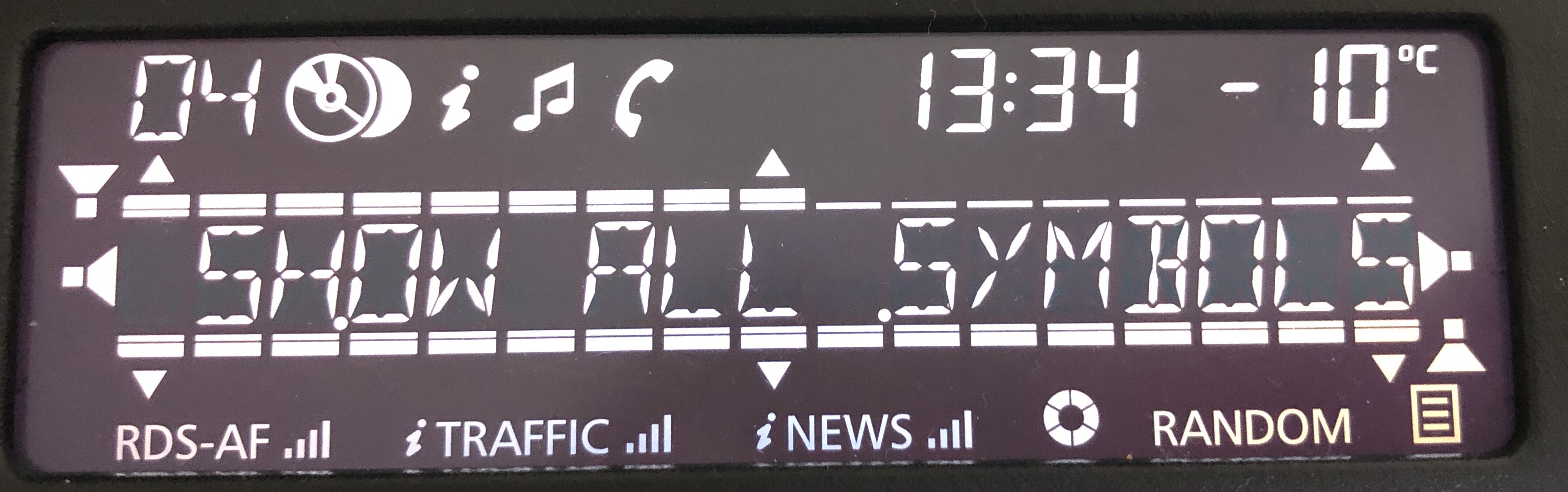
The LCD Display uses 4 Bars, 6 Arrows, 4 Speakers and Text to create some kind of a menu structure. All of these symbols and bars can be set individually. The LCD Display can show any symbols or bars at any time. We just have to set the specific bit for a symbol or bar and it will show up. This will give you a wide range of flexability on how to show menus. Thin and thick bars above and Below the Text will indicate "boxes" and "highlights" OR they will be used as bars (fader, balance, Bass Treble ...)
Scenic cluster and TomTom Navigation do not have the limitation of a segmented LCD display and can show a nicer menu structure wich is more specific to the content. Scenic cluster and TomTom use Byte1 in Consecutive frame 9 as a "message Type". Byte1 can be 0x00 (0) - 0x1D (29). Here we have 30 different pages to show all possible menus the radio is abled to generate. Another difference is that the "bars" "speakers" and "arrows" used for the LCD display are not shown here. But some parts of these elements are used to control the elements on the pages. Also not all Symbols will show up on all pages. The last bigger difference is the "modifier". On the LCD display the "modifier" will just show "cd" or "cd changer" symbol. On Scenic cluster and TomTom the "modifier" works different. In addition to "cd" and "cd changer" we also have a "fm" and "aux" modifier. This modifier will change some of the pages. On a couple of pages we get different Texts.
Scenic cluster an TomTom have a "big" and "small" display mode. We can define if the message will show up as a full page or just as a status bar. This is not used on the LCD Display.
The last slight difference is between Scenic cluster and TomTom Navigation... Scenic cluster is a little bit tighter in its restrictions. TomTom will show more of the Text on nearly all of the pages. Also Scenic cluster has many fixed names displayed on each page .
But i will point out all differences and provide examples for every case in the upcoming Project.
Ok, let´s go:
The fixed stuff that never changes:
- In general Byte0 in all messages of this "block" contain an "identifier".
0x10 to show this is a split up "block" with more then 1 message.
0x21 - 0x29 are the numbering of each following message of this "block".
This is "ISO-TP" and we replicate these Bytes for our messages.
- Byte 1 in the First Frame (line 2) tells us the length of the complete "block"
0x3F converted from HEX to Decimal is 63.
63 Bytes will follow AFTER the length EXCLUDING the "identifiers" !
Data : First Frame : Byte 2 - 7 (6) / Consecutive frame 1 - 8 : Byte 1 - 7 (56) / Consecutive frame 9 : Byte 1 (1)
6 + 56 + 1 = 63 ... The length is fixed and we replicate it.
- Byte 2 in the First Frame is always 0x40. And Bytes 2 - 7 in Consecutive frame 9 are always 0x81 filler Bytes.
Thats it for the fixed stuff ... Lets start with the interesting part:
Bytes that are changing:
Visability control:
Byte 3 4 and 5 in the first frame control if and how the message is shown. Bytes 3 and 4 enable or disable if the Message / Text is shown. If Bit0 in Byte3 and Bit4 in Byte4 are 1 the Text set in the message will be displayed. If they are 0 the text is not shown on the LCD display / the message will not show up on scenic cluster and TomTom. If Bit7 in Byte5 is 1 the message will show up as a full page. If it is 0 the message will go to the status bar (not used on LCD Display). Bit5 and Bit6 in Byte5 have no effect in my tests. Bit6 is 0 and Bit5 is 1 on all pages. EXCEPT from some Settings pages where Bit6 is 1 and Bit5 is 0. On an empty message that should not display Bit6 and Bit5 are 0.
BARS:
Byte 6 and 7 in the first frame and Bit7 in Byte 1 in Consecutive frame 1 represent the top thin bar. Each Bit we set to 1 will show one of the 17 available elements of the bar.
Byte 2 3 and Bit7 of Byte4 in Consecutive frame 1 represent the bottom thin bar. it works like the top thin bar.
Byte 5 and Bit7 of Byte6 in Consecutive frame 1 represent the top thick bar. This bar has only 9 elements and is only above the left side of the text on the LCD Display.
Byte 1 2 and Bit7 of Byte3 in Consecutive frame 2 represent the bottom thick bar. This bar also works like both thin bars.
SPEAKERS:
Byte 4 in Consecutive frame 2 is responsible for showing the Speaker symbols on the LCD Display (not used on Scenic cluster and TomTom). If Bit0 is 1 the "right" speaker is shown. If Bit3 is 1 the "left" speaker is shown. If Bit2 is 1 the "front" speaker is shown. if Bit1 is 1 the "rear" speaker is shown. To not show the symbols the bits are set to 0.
DOTS AND ARROWS:
Byte 5 in Consecutive frame 2 sets up the 6 Arrows and 2 Dots that can be displayed on the LCD Display. The Dots are only used in messageType 0x00 on Scenic cluster. And the Arrows will show up differently on Scenic Cluster and TomTom. Bit0 - Bit5 are used to set the shown Arrow. Bit6 and Bit7 are responsible to show the 2 Dots. If the Bits are 1 the symbols are shown. It they are 0 they are not shown.
SYMBOLS:
Byte 7 in Consecutive frame 2 contains some symbols that we can show. Bit4 Bit5 and Bit6 are used to show the "i" and "music note" symbols. These symbols are used to indicate if we are in a sound settings menu (music note) or in a menu for settings about RDS and so on (i symbol). If we want to show one of those symbols Bit4 is 1. If we want to show the "i" symbol Bit6 is 1, If we want to show the "music note" symbol Bit5 is 1. LCD display can show both at the same time... Scenic cluster and TomTom not. If no "i" or "music note" is shown all 3 Bits are 0. The next symbol hiding here is the "NEWS" Symbol. On the LCD Display this symbol is shown as a "NEWS" textsymbol and it can display a tiny antenna next to it (in case the Radio station you listen to supports this feature). On Scenic cluster this symbol is "colour coded". If you set the bits to just show the "NEWS" symbol without Antenna the symbol on Scenic cluster is ORANGE. If you set the Bits to show the "NEWS" Symbol and the Antenna on Scenic cluster the symbol is shown in GREEN. If you set Bit2 to 1 and Bit3 to 0 the "NEWS" symbol is shown (orange on Scenic cluster). If you set Bit2 and Bit3 to 1 the "NEWS" symbol and the Antenna is shown (green on Scenic cluster). On the LCD Display you can set the Antenna seperate from the "NEWS" symbol...
BYTE 2 in Consecutive frame 3 has another 3 sybols to offer. Bit2 and Bit3 control the "TRAFFIC" symbol wich works like the "NEWS" symbol i explained above. BIT4 and Bit5 control the "RDS" symbol wich also works like the "NEWS" symbol. Bit6 and Bit7 set the loading symbol. If Bit6 is 1 and Bit7 is 0 we display a static loading symbol. If Bit6 and Bit7 are 1 the loading symbol is animated to spin.
BYTE 3 in Consecutive frame 3 is used for 2 more symbols and the "Modifier" i talked about in the "ATTENTION" part... To show the "List" symbol we set Bit6 to 1. To show the "RANDOM" symbol we set Bit4 to 1. The "Modifier" uses Bit0 Bit1 Bit2 and Bit3. For "FM modifier" we set Bit0 to 1. For "CD modifier" we set Bit1 to 1. For "CD CHANGER modifier" we set Bit1 and Bit2 to 1. For "AUX modifier" we set Bit3 to 1. All not mentioned Bits are 0 in each case.
BYTE 4 in Consecutive frame 3 is responsible to show the "PHONE" symbol. If we set Bit0 to 1 the symbol is shown.
TEXT:
Starting from BYTE 5 in Consecutive frame 3 up to (and including) BYTE 7 in Consecutive frame 8 we have 38 Bytes for Text. For the LCD display we only use every second Byte to hold one (extended) ASCII character. LCD display will only show UPPERCASE for upper and lowercase letters. Scenic cluster and TomTom can show upper and lowercase. The usable Bytes are populated with 0x20 (space) in the example. The Byte before that can only be used by the Scenic cluster. it extends the (8Bit) ASCII Byte to a (16Bit) UTF-16 character. Not the full UTF-16 character set is implemented but there are some nice ones hidden in there.
The first two characters are used in the upper line on the LCD Display. On Scenic cluster and TomTom the will show up or not depending on the message type we use...
Thats everything. You now know what each Bit and Byte can do.
I have created a whole "Framework" in the Arduino IDE to control each state from a simple to use variable. Lots of example code and annotations for everything. I used the most basic code i could come up with to make the flow of the code as clear as possible. The framework can be set up to work freely for the LCD display or is more restricted for the Scenic cluster. You can also simulate the car (display brightness, outside temperature, set the clock, wake the display) if you just want to use the LCD Display as a standalone thing... I´m in the process of finishing the code and getting it a little bit nicer looking before i post it on Github. When everything is done i will publish a Project here and link to all of those Pages i have created here as some background information. Stay tuned.
Discussions
Become a Hackaday.io Member
Create an account to leave a comment. Already have an account? Log In.